General Administrative Information and Operations
Switch Models
Cisco Small Business 200 1.1 Series Smart Switch Administration Guide 46
6
• Custom Login Screen Settings—If you want text to be displayed on the
Login
page, enter the text in the Login Banner text box. Click Preview to
view the results.
NOTE When the user defines a login banner from the web interface, it also
activates the banner for the CLI interfaces (Console, Telnet, and SSH).
STEP 3 Click Apply to set the values in the Running Configuration file.
Switch Models
All models can be fully managed through the web-based switch configuration
utility.
Layer 2 is the default mode of operation for all devices. In Layer 2 mode, the
switch forwards packets as a VLAN aware bridge. In Layer 3 mode, the switch
performs both IPv4 routing and VLAN aware bridging.
When the switch operates in Layer 3 mode, the VLAN Rate Limit, and QoS policers
are not operational. Other QoS Advanced mode features are operational.
Fast Ethernet (10/100) ports are designated as FE and Gigabit Ethernet ports (10/
100/1000) are designated as GE in the table below.
NOTE Acronyms used for port descriptions have varied across software versions. In
release 1.0, 'e' was used for fast Ethernet, 'g' for 'gigabit Ethernet' in the GUI.
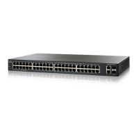
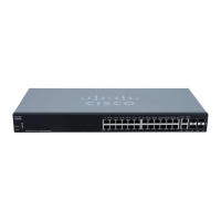
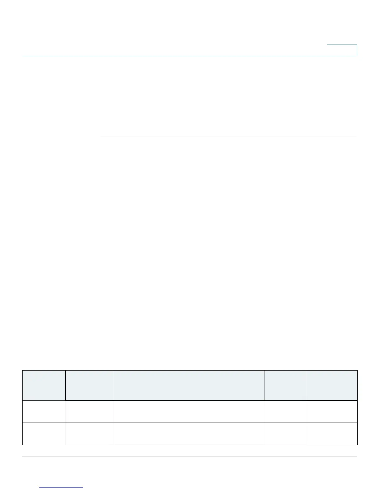
The following table describes the various models, the number and type of ports
on them and the number of ports that support PoE.
Smart Switch Models
Model
Name
Product ID
(PID)
Description of Ports on Device Power
Dedicated
to PoE
No. of Ports
that Support
PoE
SG200-18 SLM2016T 16 GE ports + 2 GE special-purpose combo
ports
SG200-26 SLM2024T 24 GE ports + 2 GE special-purpose combo-
ports
 Loading...