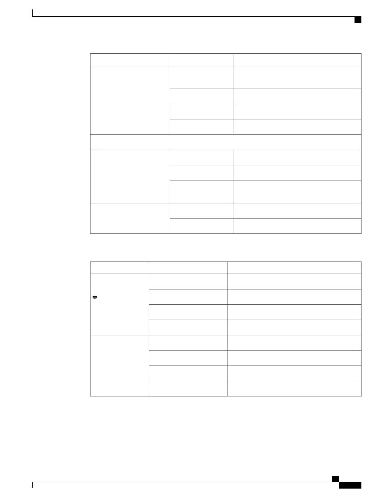
EasyManuals Logo

Cisco UCS 5108 Installation Guide

Cisco UCS 5108
114 pages
To Next Page IconTo Next Page
To Previous Page IconTo Previous Page
Page #49 background imageLoading...
Page #49 background image
DescriptionColorLED
No power to the chassis or the fan module was
removed from the chassis.
OffFan Module
Fan module restarting.Amber
Normal operation.Green
The fan module has failed.Blinking amber
Power Supply
No power to the slot.OffOK
Normal operation.Green
AC power is present but the PS is either in
redundancy standby mode or is not fully seated.
Blinking green
Normal operation.OffFail
Over-voltage failure or over-temperature alarm.Amber
Table 3: I/O Module LEDs
DescriptionColorLED
No power.OffBody
Normal operation.Green
Booting or minor temperature alarm.Amber
POST error or other error condition.Blinking amber
Link down.OffPort 1-4
Link up and operationally enabled.Green
Link up and administratively disabled.Amber
POST error or other error condition.Blinking amber
Cisco UCS 5108 Server Chassis Installation Guide
37
Overview
Interpreting LEDs

Table of Contents

Other manuals for Cisco UCS 5108

Questions and Answers:

Question and Answer IconNeed help?

Do you have a question about the Cisco UCS 5108 and is the answer not in the manual?

Cisco UCS 5108 Specifications

General IconGeneral
Number of Blade Slots8
I/O Module Bays2
Supported Blade ServersCisco UCS B-Series Blade Servers
Power Supply OptionsUp to four hot-swappable power supplies (AC or DC)
CoolingRedundant hot-swappable fans
ManagementCisco UCS Manager
Blade Slots8
Fabric InterconnectsCisco UCS 6100 or 6200 Series
Power SuppliesUp to 4 hot-pluggable power supplies
Form Factor6RU rack-mountable

Related product manuals