APPPENDIX A:
Voice and fax boards
137
Hardware settings
Do the following procedures as you install voice boards.
To set the SW100 switch
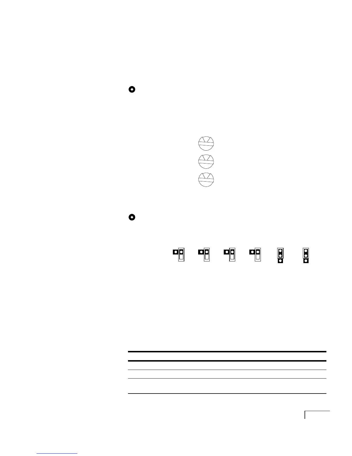
For each Dialogic PCI voice board that has a rotary switch,
set the switch to a unique value starting with 1 and con-
tinuing in sequence. For example, set the switch on the first
three PCI voice boards in the Unity server as shown below.
Install the boards in the server in the same order.
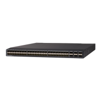
To set jumpers JP2 to JP7
Set jumpers JP2 to JP5 to “Off” on each board. For jumpers
JP6 and JP7, install shunts on the top two pins (1 and 2).
Software settings
None.
LED status indicators
The D/240PCI-T1 includes the following status indicators.
First PCI board
Second PCI board
Third PCI board
JP2 JP3 JP4 JP5 JP6 JP7
Setting
Color Lit
Green The board is powered up and receiving an external signal
Yellow Loss of frame synchronization at far end external network
Red Loss of frame synchronization on incoming line from external
network
1
2
3