APPPENDIX A:
Voice and fax boards
141
The CP4/LSI Series 2 fax board is also known as the CPi/400.
Hardware settings
Do the following procedure as you install fax boards.
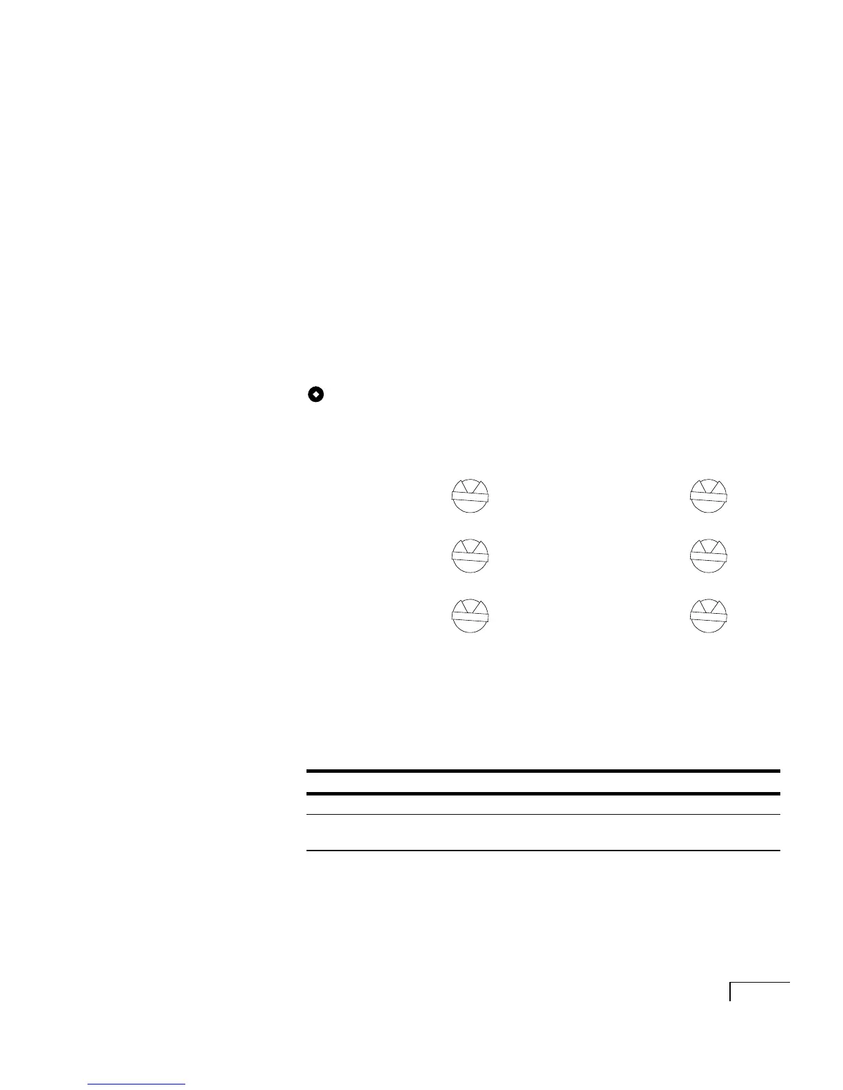
To set the rotary switch
The rotary switch setting determines the fax ports’ I/O
addresses.
The CP4/LSI Series 2 board contains four fax ports. Depending
on the configuration of the Unity server and on whether Active-
Fax is installed on a separate server, you can install up to eight
CP4/LSI Series 2 boards.
Set the rotary switch on each board as shown below.
LED status indicators
There are two LED status indicators for each fax port. The fol-
lowing table describes the meaning of the status indicators.
Rotary
switch
Rotary
switch
First board
Ports 0–3
Fourth board
Ports 12–15
Second board
Ports 4–7
Fifth board
Ports 16–19
Third board
Ports 8–11
Sixth board
Ports 20–23
Color Lit Unlit Blinking
Green Port is off hook Port is on hook ---
Amber Board is
operational
Board is not
operational
Board configuration
problem
0
3
1
4
2
5