APPPENDIX A:
Voice and fax boards
143
Hardware settings
Do the following procedure as you install fax boards.
WARNING! Do not remove the cover from the server or expansion
chassis while the power is on, if a CPD/220 fax board is already
installed. The voltage level from the board can cause injury.
WARNING! Never connect a loop-start phone line to a DID fax
port. The voltage in the loop-start line will damage the fax board. If
you are unsure whether the line is a loop-start line, test it with a
volt meter to confirm that there is no voltage.
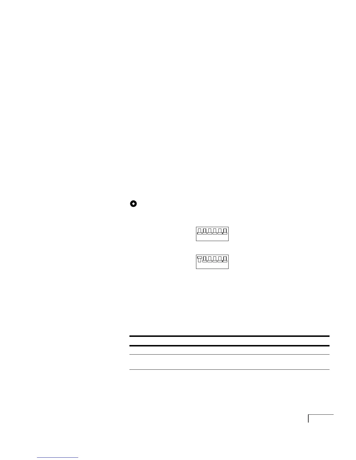
To set switch block SW1
The switch block SW1 settings determine the fax ports’ I/O
addresses.
The CPD/220 board contains four fax ports. Depending on the
configuration of the Unity server, you can install up to two
CPD/220 boards.
Set the SW1 switches on each board as shown below.
LED status indicators
There are two LED status indicators for each fax port. The fol-
lowing table describes the meaning of the status indicators.
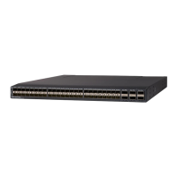
SW1
First board
Ports 0–3
Second board
Ports 4–7
Color Lit Unlit Blinking
Green Port is off hook Port is on hook ---
Amber Board is
operational
Board is not
operational
Board configuration
problem
1234
5 6
On
Off
1234
5 6
On
Off