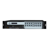
Citrix ADC MPX
• Two 10G/1G SFP+ Ethernet Ports, numbered 10/1 to 10/2 from le to right.
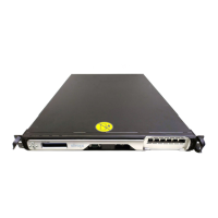
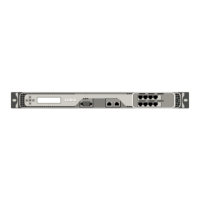
The following figure shows the back panel of the MPX 59xx appliance.
Figure 2. Citrix ADC MPX 59xx, back panel
The following components are visible on the back panel of the MPX 59xx appliances:
• One 240 GB removable solid-state drive (SSD).
• Power switch, which turns power to the appliance on or o.
– Ifthe OS is functional, press the switch for less than two seconds to power down the system
with a graceful shutdown.
– If the OS is not responsive, press the and hold the power switch for more than 4 seconds
to force the power o.
• One power supply, rated at 450 watts, 100-240 VAC (second power supply for redundancy is
a customer installable option). Maximum power consumption is 340 watts and typical power
consumption is 300 watts. Each power supply has an LED indicating its status, as described
below:
LED Color LED Indicates
OFF No power to any power supply in the
appliance.
Flashing RED No power to this power supply.
Flashing GREEN Power supply is in standby mode.
GREEN Power supply is functional.
RED Power supply failure.
• Disable alarm button, which is functional only when the appliance has two power supplies.
Press this button to silence the power alarm when one of two power supplies loses input power
(second power supply optional) or when a power supply is malfunctioning.
• Non-Maskable Interrupt (NMI) Button, used at the request of Technical Support to initiate a core
dump. To press this red button, which is recessed to prevent unintentional activation, use a pen,
© 1999-2019 Citrix Systems, Inc. All rights reserved. 31
 Loading...