6
Chapter 2: Description of products and accessories
Power supply units and system connection accessories
-V
-V
N
L
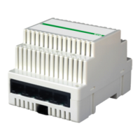
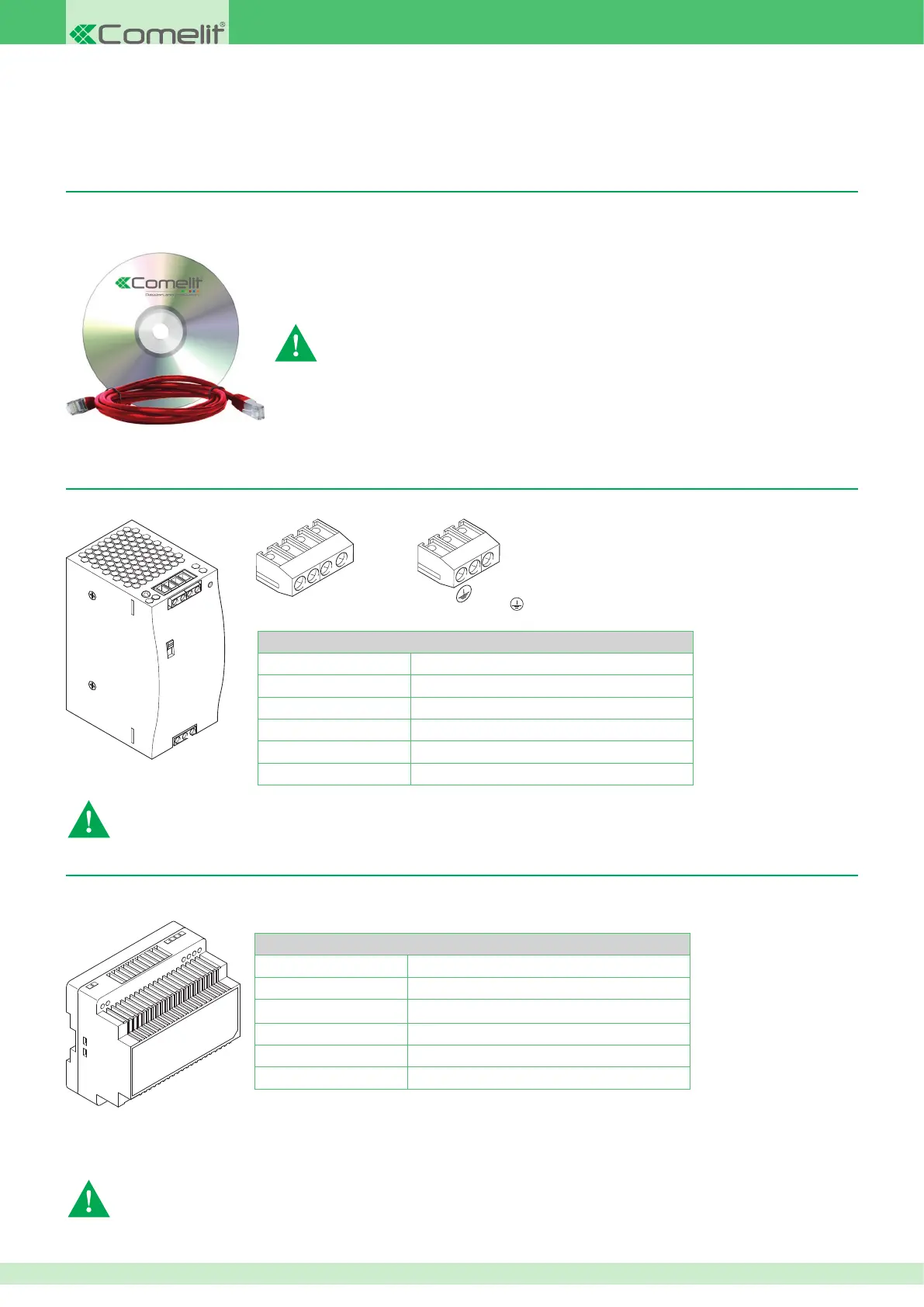
Power supply unit Art. 1441A, to power all accessories connected to the riser (not including external units).
Tec hni cal ch ara cte ris tic s
Input voltage
100 - 240 V~ (3 A)
Output voltage 48 V DC (2.5 A)
Power 120 W
Frequency 50/60 Hz
Tem per atu re thr esh old s -30°C / +55°C
Dimensions 4 DIN modules / H: 12.5 cm W: 6.5 cm D: 10.7 cm
VIP system riser power supply unit 120 W Art. 1441A
Ter mi na l b lo ck s f or con ne ct ion
+V +V -V -V: Riser power supply terminals.
L N: Alternating 230 V~ network terminals.
: Earth. connection terminal.
Ter mi na l b lo ck s f or con ne ct ion
+V -V: Riser power supply terminals.
L N: Alternating 230 V~ network terminals.
Power supply unit Art. 1441, to power all accessories connected to the riser (not including external units).
Tec hni cal ch ara cte ris tic s
Input voltage
100 - 240 V~ (3 A)
Output voltage 56 V DC (1.8 A)
Power 100 W
Frequency 50/60 Hz
Tem per atu re thr esh old s -30 +55
Dimensions 6 DIN modules / H: 9.3 cm W: 9.9 cm D: 5.3 cm
VIP system riser power supply unit 100 W Art. 1441
Software
CD-ROM software for PC installation, for the programming and conguration of all wired devices in the system. Also allows button programming and
management of names in external unit directories. Includes a special cable for connection between switch 1440 and PC.
When connecting a PC to a VIP system, the special cable supplied with software Art. 1449
must be used
VIP Manager Art. 1449 VIP system conguration software
• Install the equipment by carefully following the instructions given by the manufacturer and in compliance with the standards in force. Do not tamper with the internal elements
offering protection against short circuits and overcurrents.
• The electrical system of the building must be tted with an (easily accessible) omnipolar mains switch with a contact opening of at least 3 mm, which is capable of cutting off
the power supply of the device.
• Install the equipment by carefully following the instructions given by the manufacturer and in compliance with the standards in force. Do not tamper with the internal
elements offering protection against short circuits and overcurrents.
• The electrical system of the building must be tted with an (easily accessible) omnipolar mains switch with a contact opening of at least 3 mm, which is capable of cutting
off the power supply of the device.