7
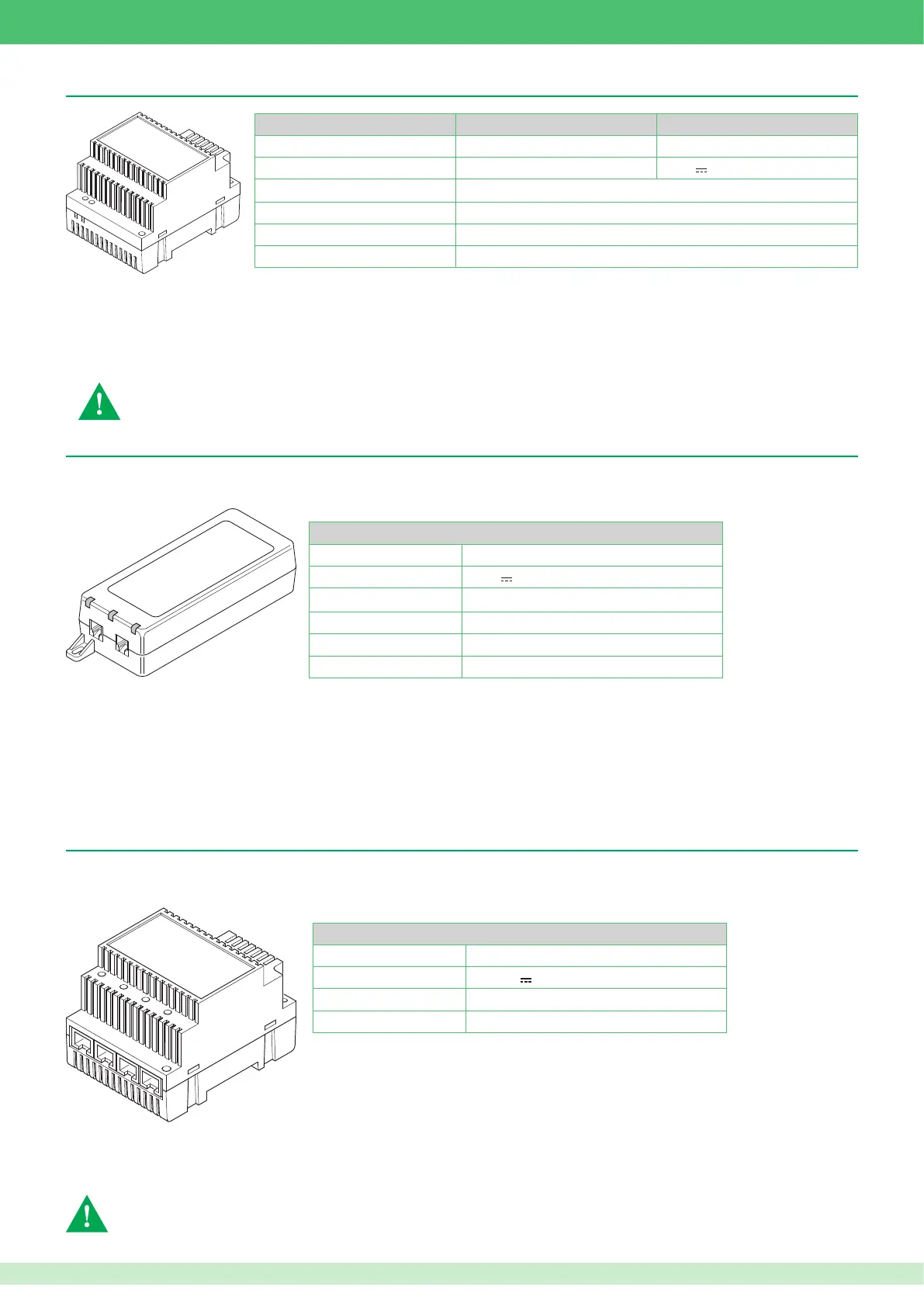
Power supply unit Art. 1395 / Art. 1595 for external units
VIP system POE power supply unit for monitor Art. 1451
The power supply unit converts an Ethernet connection into a POE-type connection supplying an internal unit. The power supply unit is necessary if
VIP devices (door entry monitors / door-entry phones) are installed on existing Ethernet networks with non-POE (Power Over Ethernet) connections.
Indicator LED
ON: Power supply enabled indication
FAULT: Error indication
CONNECT: Ethernet cable connected to OUT port indication
Tec hni cal ch ara cte ris tic s
Input voltage
100 - 240
V~
(0.95 A)
Output voltage
56
V
(0.35 A)
Power 33.6 W
Frequency 50 - 60 Hz
Tem per atu re thr esh old s -20 / +50°C
Dimensions H: 3.7 cm W: 6.5 cm D: 16.4 cm
Ethernet ports
OUT: for the connection of internal units
IN: for the connection of a non-POE Ethernet network
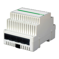
Switch Art. 1440
The Ethernet Switch module Art. 1440 performs two main functions:
• Directing data VIP system data packages.
• Provide a power supply for the extensions connected to it and to any switch/repeaters connected in cascade.
Tec hni cal ch ara cte ris tic s
Absorption Min. 0.7 W Max. 2.6 W
Power supply
36/57 V 3A Max.
Tem per atu re thr esh old s -30 / +55°C
Dimensions 4 DIN modules / H: 6.2 cm W: 7.2 cm D: 9 cm
Ethernet port status indicator LED
Lit steadily: port in standby
Flashing: data passing through the port
Off: port not connected
IN1 IN2 100 Mb riser Ethernet ports. Used for the connection of distributors, such as repeaters, switches, internal units etc.
OUT1 OUT2 OUT3 OUT4: 10 Mb extension Ethernet port. Used for the connection of distributors, such as repeaters, switches, internal units etc.
+ -: External power supply terminals. Connection of power supply unit Art. 1441 or Art. 1441A
For correct operation of the system protecting Art. 1440, the riser must be connected with input on port IN1 and
output on port IN2
Tec hni cal ch ara cte ris tic s
Art. 1395 Art. 1595
Input voltage
207 - 257 V~ (3 A) 120-230 V~ (0,8 A)
Output voltage
12 V~ (1,8 A) 33 V ± 3% (0,5 A)
Power
60 W
Frequency
50/60 Hz
Tem per atu re thr esh old s -20 / +40°C
Dimensions 4 DIN modules / H: 9 cm W: 7.15 cm D: 6.2 cm
Terminal blocks for connection Art. 1395
230V ~:
Alternating 230 Vac network terminals.
0 12~:
Power supply output terminals.
Terminal blocks for connection Art. 1595
120-230 V ~
: Power supply terminals.
+ -
:
Power supply output terminals.
• Install the equipment by carefully following the instructions given by the manufacturer and in compliance with the standards in force. Do not tamper with the internal elements
offering protection against short circuits and overcurrents.
• The electrical system of the building must be tted with an (easily accessible) omnipolar mains switch with a contact opening of at least 3 mm, which is capable of cutting
off the power supply of the device.