Setting Up a Replacement Controller 9
October 2013 GB 57 /80
9 SETTING UP A REPLACEMENT
CONTROLLER
9.1 The Setup Code and
Compressor Identification
Number
NOTICE
Material damage
The setup code and identification number are
unique to each compressor. If a setup code from
another compressor is used, the compressor is
incorrectly configured, which can lead to consid-
erable compressor damage.
➯
Under no circumstances must data from an-
other compressor be used.
NOTE
It is recommended that setup code and com-
pressor reference number are noted down and
these made available before the controller is
switched on.
DANGER
Electric shock
Life-threatening electric shock
➯
Work on the electrical equipment
must only be carried out by autho-
rised electricians or electrical techni-
cians.
➯
With the speed-controlled types (
RS ) there is a risk of electric shocks
due to charged capacitors!
Switch the compressor to a zero
volts state and wait 10 minutes be-
fore touching any electrical parts.
➯
Checking the DC bus voltage.
The setup code
The setup code defines all the basic factory com-
pressor settings.
The setup code comprises 16 characters. The
setup code is located on a sticker inside the switch
cabinet.
Compressor identification number
The compressor reference number is the com-
pressor serial number.
The compressor reference number comprises 13
characters and starts "CD". The compressor refer-
ence number is located on the nameplate.
9.2 Setting up a replacement
controller
Changing controller
DANGER
Elektrischer Schlag
Lebensgefährliche elektrische Spannung
➯
Arbeiten an der elektrischen Ausrüs-
tung dürfen nur von autorisiertem
elektrotechnischem Fachpersonal
durchgeführt werden.
➯
Bei den Drezahlgeregelten Typen "
RS " besteht Elektroschockgefahr
durch geladene Kondensatoren!
Den Kompressor spannungsfrei
schalten und 10 Minuten warten,
bevor elektrische Bauteile berührt
werden.
DC-Busspannung überprüfen.
1 Switch the main switch OFF.
2 Open the switch cabinet door and swing suffi-
ciently open.
3 Remove the electrical connections.
4 Remove the nuts from the studs.
5 Take out the controller.
6 Insert the replacement controller and secure
using the nuts.
7 Plug in the electrical connections.
8 Close the switch cabinet door.
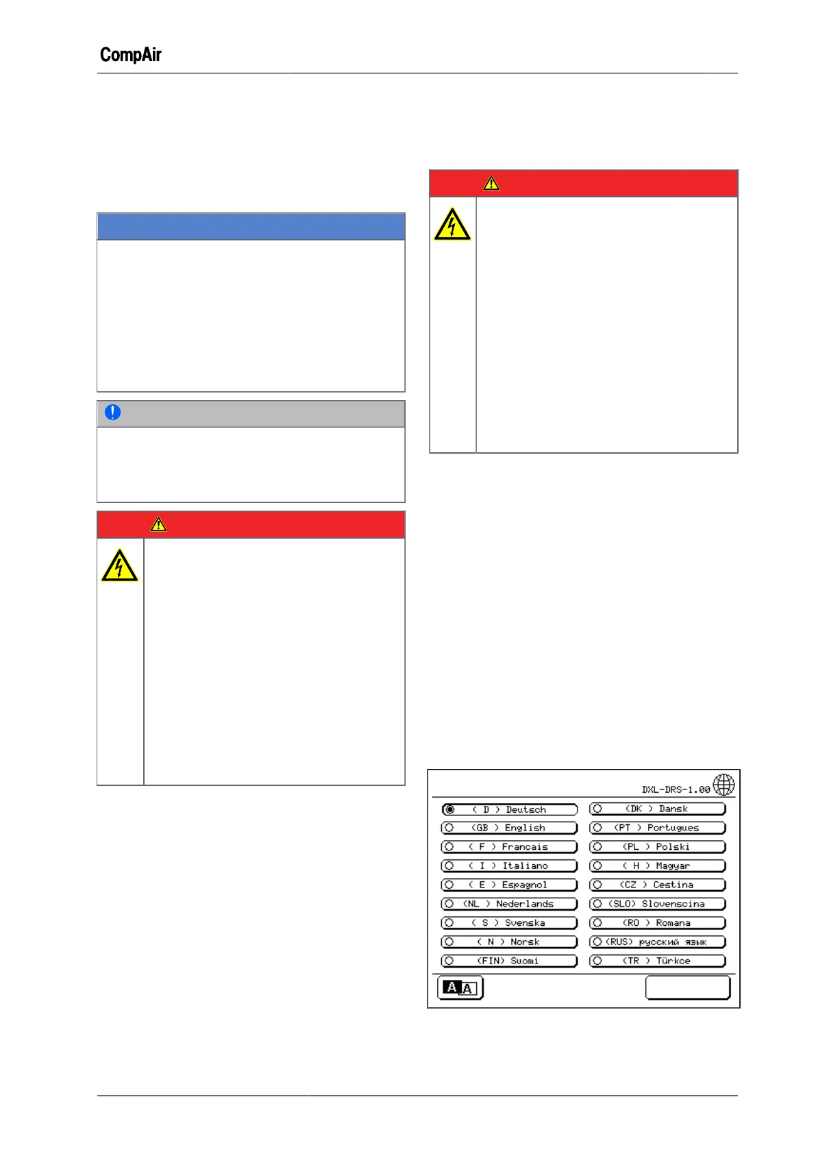
Switching on the replacement controller for
the first time
1 Switch the main switch ON.
–
The menu "Choose Language" appears.
Fig. 9-1: Menu "Choose Language"
 Loading...