Base Load Sequencing (BLS) 10
October 2013 GB 69 /80
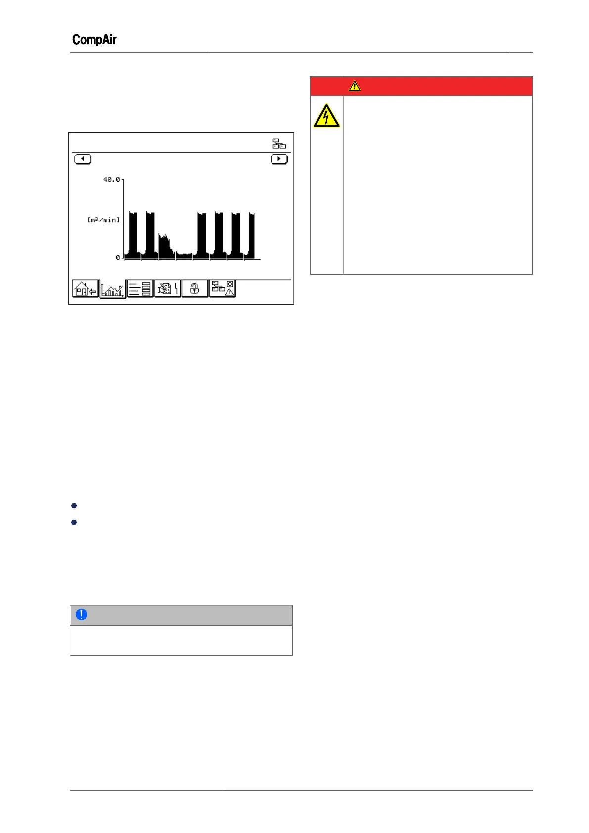
This graph shows the variation in the volume flow
of the base load sequencing group over a speci-
fied period.
Statistics Weekly Profile (BLS)
Trends
Average Volume Flow
We.
Th. Fr. Sa. Su.
Mo.
Tu.
We.
20 Feb.
Statistics Weekly Profile (BLS)
Fig. 10-14: Graph "Statistics Weekly Profile (BLS)"
This bar graph shows the average hourly volume
flow of the base load sequencing group over the
last 8-days.
10.9 RS485:3 module installation
This chapter explains how to retrofit the RS485:3
module if it has not already been installed in the
controller ex-factory. If the module is already in-
stalled, the "X08" connector will be visible at the
back of the controller.
The RS485:3 module extends the controller by the
addition of a third RS485 interface.
Ordering information:
Part number: ZS1075506
Scope of supply:
– RS485:3 module
– Connector kit for slave controllers
– Installation manual for the RS485:3 module
Installation
NOTE
To install the RS485:3 module also observe the
installation manual for the RS485:3 module.
DANGER
Electric shock
Life-threatening electric shock
➯
Work on the electrical equipment
must only be carried out by autho-
rised electricians or electrical techni-
cians.
➯
With the speed-controlled types (
RS ) there is a risk of electric shocks
due to charged capacitors!
Switch the compressor to a zero
volts state and wait 10 minutes be-
fore touching any electrical parts.
➯
Checking the DC bus voltage.
1 Switch the main switch OFF
2 Open the switch cabinet door and swing suffi-
ciently open.
3 Disconnect all connections from the controller.
4 Take off the controller cover.
5 Plug the RS485:3 module into the provided
sockets.
6 Ensure that all pins are in the socket and not
beside it.
7 Close the controller cover.
8 Make all connections to the controller.
9 Close the switch cabinet door.
Wiring Method
We strongly recommend that you use shielded
and twisted pair (TP) cables (types 2 x 2 x 0.25 to
0.75 mm
2
).
Total bus wiring length must not exceed 1200 m.
The RS485 interfaces of the master and the slave
compressor controllers should form a bus struc-
ture, i.e. all compressors should be connected in
series.
The following image shows examples of correct
and incorrect wiring of the compressor station.
 Loading...