10 Base Load Sequencing (BLS)
70 / 80 GB October 2013
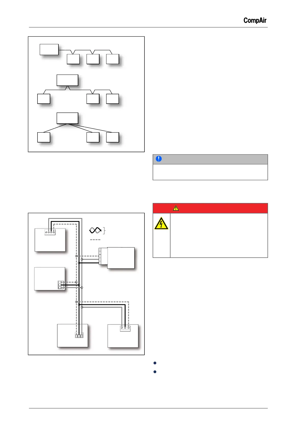
Fig. 10-15: Wiring the compressors
Circuit diagram
During installation, refer to the terminal numbers
shown on the appropriate connector only, i.e. not
to any other marking on the slaves. The following
image shows examples of all supported hardware
models. The DELCOS XL Master can control up to
a maximum of 3 slaves.
Fig. 10-16: Circuit diagram
Set Up the Slave Compressor Controller Com-
munication Parameter
The appropriate minimum required software ver-
sion must be installed on the controllers in order
for them to operate correctly. See table "Required
software versions".
Set the communications parameters on the slave
controllers as follows:
1 Set the RS485 protocol to ModBus. See oper-
ating instructions for slave control.
2 Set the slave baudrate to "9600". See operat-
ing instructions for slave control.
3 Set the RS485 address of the slave. See oper-
ating instructions for slave control.
The necessary RS485 address is indicated on
the button <Compressor> in the menu "Base
Load Sequencing (BLS)".
NOTE
The STD module is configured using DIP
switches. See the following chapter.
10.10 Installing the compressor
module (STD)
DANGER
Electric shock
Life-threatening electric shock
➯
Work on the electrical equipment
must only be carried out by autho-
rised electricians or electrical techni-
cians.
General
The compressor module (STD) is used to con-
nect any other controller such as the DELCOS XL,
DELCOS PRO or DELCOS 3100 to the DELCOS
XL Master. The module is connected to the master
via the integrated RS485 interface.
The status of the compressor is detected by digital
inputs of the compressor module and sent to the
master via its RS485 interface.
In addition, commands for the control of the com-
pressor are transmitted from the master to the
compressor module (STD) via the RS485 interface
and are executed by the digital outputs.
Ordering information:
Part number: 100016166
Scope of supply:
– Compressor module (STD)
– RS485 connector
 Loading...