Base Load Sequencing (BLS) 10
October 2013 GB 71 /80
Technical Specification
Item Value
Supply voltage 110..230 V AC/DC ±10 %
Power consump-
tion
1 VA
Digital inputs 24..230 V AC/DC ±10 %
Digital outputs Potential-free relay outputs,
max. 240 V AC / 1 A
Ambient tempera-
ture
Operation 0 to 55 °C
Storage -25 to +75 °C
Dimensions
(W x H x D)
100 x 110 x 70 mm
Type of protection IP30
Assembly DIN rail TS35
Chart 10-9: Technical Specification
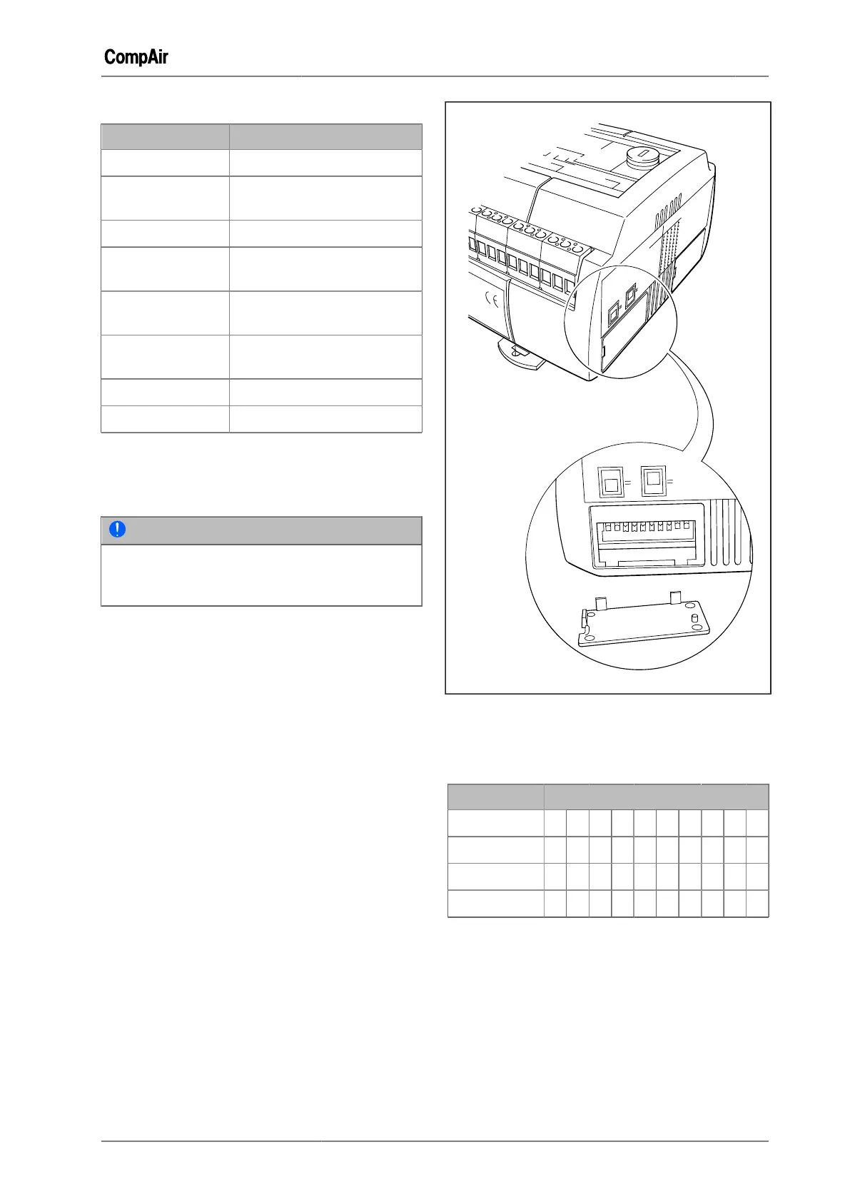
Setting the address of the compressor
module (STD)
NOTE
The DIP switches should be set prior to instal-
lation of the compressor module (STD) in the
switch cabinet.
The DIP switches are located behind a cover on
the right hand side of the module.
Fig. 10-17: Position of the DIP switch
The following table shows the necessary and valid
DIP switch settings for communicating with the
DELCOS XL Master:
Address DIP switch
1 2 3 4 5 6 7 8 9 10
2 0 1 0 0 0 0 0 0 0 0
3 1 1 0 0 0 0 0 0 0 0
4 0 0 1 0 0 0 0 0 0 0
Chart 10-10: Compressor module (STD) DIP Switch
Settings
1 = On (up)
2 = Off (down)
Fitting and installation:
The fitting and installation of the compressor mod-
ule (STD) takes place according to the local cir-
cumstances and must be undertaken by an electri-
cian.
 Loading...