HPOD C, X-, Ku-Band High-Power Outdoor Amplifier Revision 6
Table of Contents MN/HPOD.IOM
vii
C.3.2 InstallingtheNewFanAssembly..............................................................................................C–5
C.4 ScheduledMaintenance.......................................................................................................C–6
TABLES
Table2‐1.HPODSSPAExternalConnectors.............................................................................................2–3
Table2‐2.J2|RFOUTWaveguideOutputFlange...................................................................................2–4
Table2‐3.J3|ACINConnectorPinout....................................................................................................2–5
Table2‐4.J10ConnectorPinout...............................................................................................................2–6
Table2‐5.J4|REDUNDANTLOOPConnectorPinout..............................................................................2–7
Table2‐6.J6|COM1ConnectorPinout...................................................................................................2–8
TableA‐1.S
ummaryofAvailableRedundancySystemAssemblyKits.....................................................A–2
TableA‐2.UniversalPoleMountingKit(CEFDP/NPL/12319‐1)PartsList..............................................A–4
TableA‐3.HPODUnitMountingKit(CEFDP/NPL/12300‐1)PartsList....................................................A–6
TableA‐4.HP
OD1:1RedundancySystem–CommonUnistrutKit(CEFDP/NKT/12200‐1)PartsList....A–8
TableA‐5.HPOD1:2RedundancySystem–CommonUnistrutKit(CEFDP/NKT‐0000017)PartsList..A–10
TableA‐6.ODPAC‐Band1:1RedundancySwitch/WaveguideKit(CEFDP/NKT/1
1799)PartsList.......A–18
TableA‐7.ODPAX‐Band1:1RedundancySwitch/WaveguideKit(CEFDP/NKT/11387‐1)PartsList....A–20
TableA‐8.HPODC‐Band1:1RedundancySwitch/WaveguideKit(CEFDP/NKT/12201‐1)PartsList....A–23
TableA‐9.HPODC‐BandOfflineUnitTerminationBypassWavegui
deKit(CEFDP/NKT‐0020523)Parts
List...................................................................................................................................................A–25
TableA‐10.Ku‐Band1:1RedundancyAssemblyKit(CEFDP/NKT/11936‐1)PartsList.........................A–27
TableA‐11.HPODKu‐Band1:1RedundancySwitch/WaveguideKit(CEFDP/NKT/12337‐1)PartsList.......
........................................................................................................................................................A–29
FIGURES
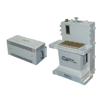
Figure1‐1.ComtechEFDataHPODSSPA.................................................................................................1–1
Figure1‐2.HPODSSPADimensionalEnvelope.........................................................................................1–3
Figure1‐3.ComtechEFDataHPODSSPABlockDiagram.........................................................................1–4
Figure2‐1.CoaxialConnectorExample....................................................................................................2–1
Figure2‐2.CircularConnectorExample...................................................................................................2–2
Figure2‐3.HPODEx
ternalConnectors.....................................................................................................2–3
Figure2‐4.HPODUnit...............................................................................................................................2–9
Figure4‐1.HPODHome|Homepage....................................................................................................4–11
Figure4‐2.Home|Contactpage............................................................................................................4–12
Figure4‐3.Home|Supportpage...........................................................................................................4–13
Figure4‐4.Admin|AccessPage.............................................................................................................4–14
Figure4‐5.Ad
min|SNMPpage.............................................................................................................4–16
Figure4‐6.Config|Amplifierpage.........................................................................................................4–17
Figure4‐7.Config|Utilitypage..............................................................................................................4–19
Figure4‐8.Config|Redundancypage....................................................................................................4–20
Figure4‐9.Status|Monitorpage ..........................................................................................................4–21
Figure4‐10.Status|Alarmspage...........................................................................................................4–22
Figure4‐11.St
atus|FETspage...............................................................................................................4–23