CSC Combination Puller/Cutter UGE048/1103
2-4 DESCRIPTION
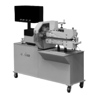
Extruded material that has been sized and cooled enters the
combination puller cutter from the upstream side. The extru-
date passes through and is positioned by guide rollers (Step 1).
Two opposing belts move the extrudate through the puller
(step 2). These belts have grooves that fit the teeth on the
rolls, preventing side-to-side movement. Belt coverings are
available in a variety of materials for your needs. Walk-
through style belt guards ensure operator safety while allow-
ing access to the belts. The belt speed is controlled by eye-
level controls.
One (model 320) or two (models 426) threaded rods control
the distance between the upper and lower belts. On 320 units,
the top and bottom belts open from a common, fixed center.
For 426 units, each belt adjusts independently, allowing the
operator to fine-tune the machine height.
Rubber grommets (320) or a 90-pound die spring (426) allow
the upper belt to 'give' slightly, preventing the puller from
being damaged by small lumps of extrudate or other foreign
objects.
After passing through the belts, the pulled material continues
on to the cutter. The cutter is mounted on linear slides that
allow as much as 6 inches of movement. The cutter can be
moved away from the puller for startup, then moved close to
the puller to enhance delivery to the cutter bushings.
The cutter's servo motor, which is positional control, is direct
coupled to an in-line planetary gear reducer and drives the
cutter head, or on L models (light duty) the cutter head is
attached directly to the servo motor.
The cutting knife, attached to the cutter head, is driven by the
servo motor. Two cutter bushings guide and support both the
extrudate and the cutting knife. The extrudate passed through
the cutter bushings and is cut by the rotating cutter head (step
3). The cutter head is mounted directly to the in-line planetary
gear reducer shaft using a Trantorque coupling device, and
may have as many as one optional blade position.
Cut pieces are collected or carried on to further processing by
an optional conveyor (step 4).
HOW THE
COMBINATION
PULLER/CUTTER
WORKS
Continued