28
5.5
You configure the input and output ports by first selecting the “
Depending on the model of your IPefono device, you can configure a specific number of inputs
and outputs.
IO
Modbus module address
TCP modbus port
UDP modbus port
Input parameters
Output parameters
Audio sensor parameters
Time in milliseconds to keep pressed
before call
F
The IPefono can have up to three inputs and two outputs (depending on the model) which are
identified with a numeric address.
protocol, widely used in control and data acquisition systems.
identifier 10000 and the outputs from 20000. This means that the inputs and outputs can be
controlled by using applications that use the MODBUS protocol, wi
configuration required.
The following table lists the identifier and the assigned port.
Model NAME
HQ/LC CALL
HQ INPUT1
INPUT2
HQ/LC OUTPUT1
HQ OUTPUT2
T
You configure the input and output ports by first selecting the “
IO” option (see
Depending on the model of your IPefono device, you can configure a specific number of inputs
1
Address of the input and output
0
TCP port to control inputs and
outputs
0
input(0)
input(1)
input(2)
output(0)
output(1)
audiosensor
Time in milliseconds to keep pressed
100
Time during which you have to
hold down the button before a
call is made, in milliseconds
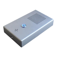
29. CONFIGURATION OF INPUT AND OUTPUT PORTS
The IPefono can have up to three inputs and two outputs (depending on the model) which are
identified with a numeric address.
That address coincides with the range used in the MOD
protocol, widely used in control and data acquisition systems.
The inputs are numbered from the
identifier 10000 and the outputs from 20000. This means that the inputs and outputs can be
controlled by using applications that use the MODBUS protocol, wi
The following table lists the identifier and the assigned port.
IDENTIFIER DESCRIPTION
10000 Input for user call button
10001
Analogue or auxiliary digital input
10002
Analogue or auxiliary digital input
20000 Output to
connect the device to open the
door
20001 Auxiliary digital output
1. ASSIGNING IDENTIFIERS FOR INPUTS AND OUTPUTS
5 – Configuration
. IPefono. V2.8
23).
Depending on the model of your IPefono device, you can configure a specific number of inputs
Address of the input and output
TCP port to control inputs and
Time during which you have to
hold down the button before a
call is made, in milliseconds
The IPefono can have up to three inputs and two outputs (depending on the model) which are
That address coincides with the range used in the MOD
BUS
The inputs are numbered from the
identifier 10000 and the outputs from 20000. This means that the inputs and outputs can be
The following table lists the identifier and the assigned port.
Analogue or auxiliary digital input
Analogue or auxiliary digital input
connect the device to open the