Menu 8
Parameter
structure
Keypad and
display
Parameter x.00
Parameter description
format
Advanced parameter
descriptions
Serial comms
protocol
Performance
120 Mentor MP Advanced User Guide
www.controltechniques.com Issue Number: 4
This parameter changes the logic polarity for digital inputs, the digital outputs, and the relay outputs.
When this parameter = 0 the digital outputs are in push-pull mode.
When this parameter = 1 either the high-side drive (negative logic polarity) or the low-side driver (positive logic polarity) is disabled.
This allows outputs to be connected in a wire-ORed configuration.
8.21 T24 digital I/O 1 source/destination
8.22 T25 digital I/O 2 source/destination
8.23 T26 digital I/O 3 source/destination
8.24 T27 digital input 4 destination
8.25 T28 digital input 5 destination
8.26 T29 digital input 6 destination
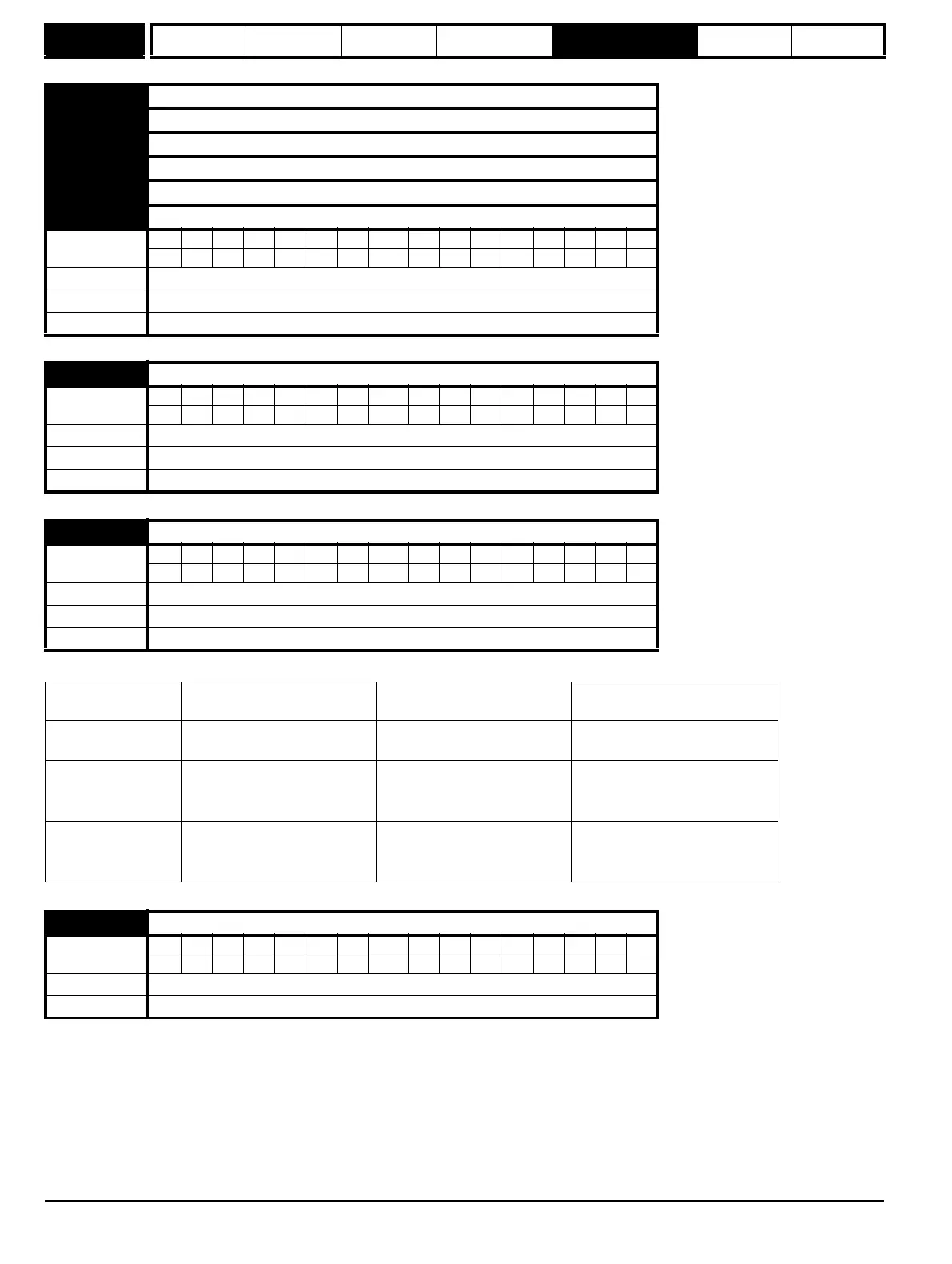
Coding
Bit SP FI DE Txt VM DP ND RA NC NV PT US RW BU PS
1 2 1111
Default See Table 5-7
Range Pr 0.00 to Pr 22.99
Update rate Read on drive reset
8.27 Relay / source
Coding
Bit SP FI DE Txt VM DP ND RA NC NV PT US RW BU PS
2 1111
Default See Table 5-7
Range Pr 0.00 to Pr 22.99
Update rate Read on drive reset
8.29 I/O polarity select
Coding
Bit SP FI DE Txt VM DP ND RA NC NV PT US RW BU PS
1 1111
Default 1
Range 2
Update rate Background read
Pr 8.29 = 0 (negative logic
inputs and outputs)
Pr 8.29 = 1 (positive logic
inputs and outputs)
Pr 8.29 = 2 (positive logic inputs
and negative logic outputs)
Inputs <5 V = 1
>15 V = 0
<5 V = 0
>15 V = 1
<5 V = 0
>15 V = 1
Non-relay Outputs On (1) = <5 V
OFF (0) = >15 V
On (0) = <5 V
OFF (1) = >15 V
On (1) = <5 V
OFF (0) = >15 V
Relay outputs OFF (0) = open
On (1) = closed
OFF (0) = open
On (1) = closed
OFF (0) = open
On (1) = closed
8.30 Open collector output
Coding
Bit SP FI DE Txt VM DP ND RA NC NV PT US RW BU PS
111
Default 0
Update rate Background read