26
CONVAID USER’S GUIDE
Fig. 37
Fig. 40
Fig. 38
Fig. 41
Fig. 39
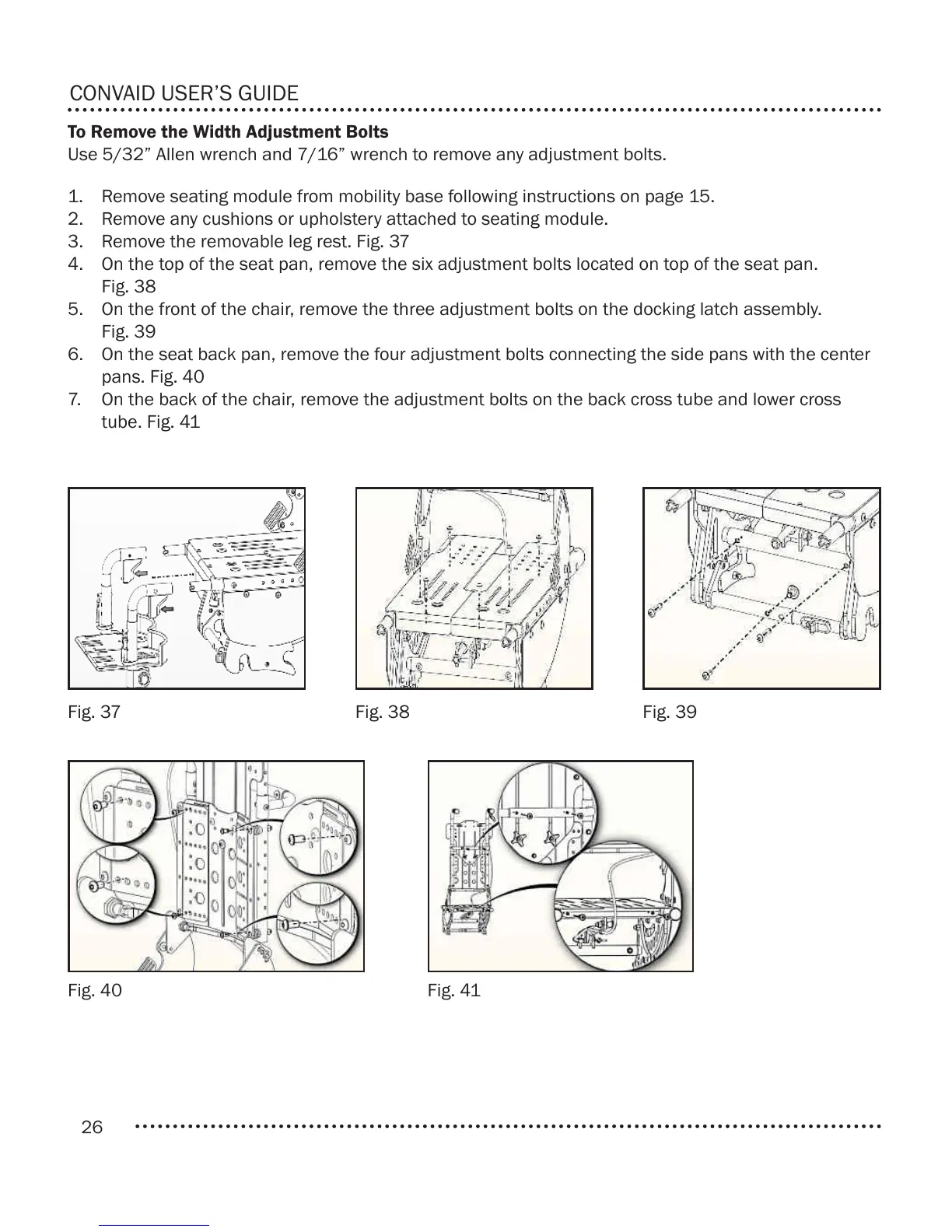
1. Remove seating module from mobility base following instructions on page 15.
2. Remove any cushions or upholstery attached to seating module.
3. Remove the removable leg rest. Fig. 37
4. On the top of the seat pan, remove the six adjustment bolts located on top of the seat pan.
Fig. 38
5. On the front of the chair, remove the three adjustment bolts on the docking latch assembly.
Fig. 39
6. On the seat back pan, remove the four adjustment bolts connecting the side pans with the center
pans. Fig. 40
7. On the back of the chair, remove the adjustment bolts on the back cross tube and lower cross
tube. Fig. 41
To Remove the Width Adjustment Bolts
Use 5/32” Allen wrench and 7/16” wrench to remove any adjustment bolts.