16 3 - Maintenance instructions
COROB
TM
D300
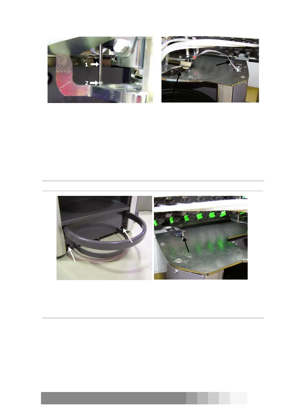
6. Open the two screws which are in lower-front-part of the can table. These screws fasten the
can table to the foot, see figure 28.
7. Lift up the fasteners which are on top of the can table and detach the upper part of the can
table. You can see the fastener on the left in figure 29 and the right one in figure 27.
8. Place the puncher handle (optional) back in place and lower the puncher blade. Now it is
easier to remove the table.
9. Pull the can table away from the COROB
TM
D300.
10. Attach the can table back in place in opposite order.
NOTE!: Make sure that the removed can table stands.
3.3 Tilting the dispensing module
Tools required:
• 2.5 mm Allen key
Procedure:
1. Switch off the COROB
TM
D300 and unplug the mains cable from the outlet.
2. Remove front casing, see instructions on page 15.
3. Remove the hydraulic can table, see “3.2 Removing the can table during service”.
4. Remove the top screw on both sides of the dispensing module, see figure 30.
Fastener
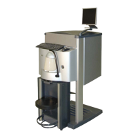
Figure 27: Detach the cable from the cable
interface.
Figure 26: The striking rod (1) is locked with a
nut (2) and they are behind the puncher blade.
Figure 29: The fastener on the left.Figure 28: The can table is attached with
two screws to the foot of the COROB
TM
D300.