3 - Maintenance instructions 23
7. Place the cylinder in position:
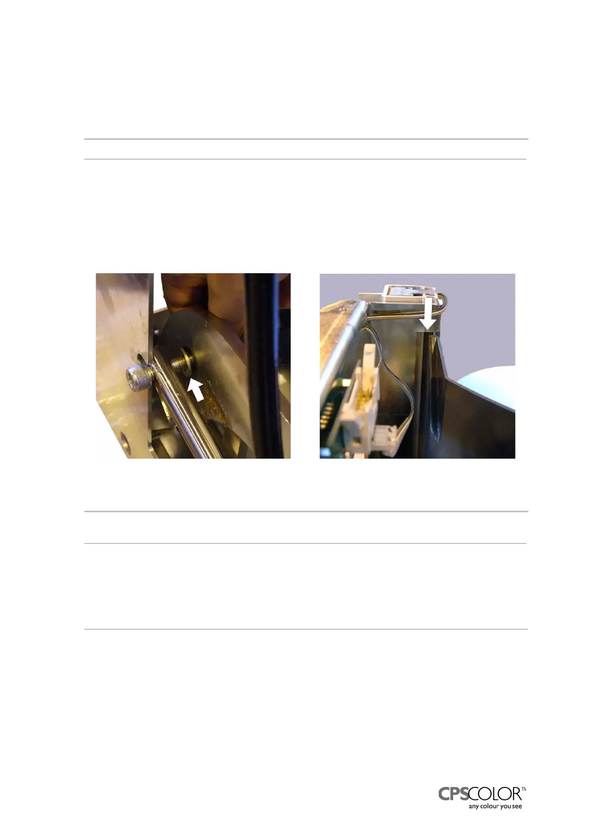
- Put a washer behind the left screw and the cylinder, see figure 47.
- Tighten the screw and open it one quarter of round.
- Screw the right screw in position, tighten and lock with a locking nut
=> open the screw one quarter of round.
NOTE!: Never tighten the cylinder screws fully!
8. Replace the plug with a filter in top of the pump, if needed.
9. Test that the can table works properly.
10. Place the back cover back in position:
- Lift the can table in upper position.
- Thread the back cover in position from the front and the lower right corner first.
- Check that the upper and lower parts of the sides are in grooves, see figure 48.
- Fasten the back cover with the screw.
NOTE!: Watch out for the wires of the can on can table -sensor, which run on top of the can table,
see figure 48.
11. Place the plastic cover on the table as far back as you can.
12. Attach the cover on top of the can table assy.
NOTE! Watch out the sensor wires are not squeezed!
13. Vent the unit following the instructions explained below.
3.7.2 Venting
If the hydraulic can table doesn't maintain it's position, there is probably air in the hose and/or in
the cylinder. The air can be removed according to the following instructions.
Procedure:
1. Remove the can table from the COROB
TM
D300.
2. Lift the can table to the upper position.
3. Tilt the can table assy on the pumps side as shown in figure 49.
4. Press the table down.
5. Lift and lower the table three times.
Figure 48: The back cover is placed in the
groove of the frame.
Figure 47: Fastening the cylinder rod to the
can table assy.