32 3 - Maintenance instructions
COROB
TM
D300
3.10Replacing a sensor
COROB
TM
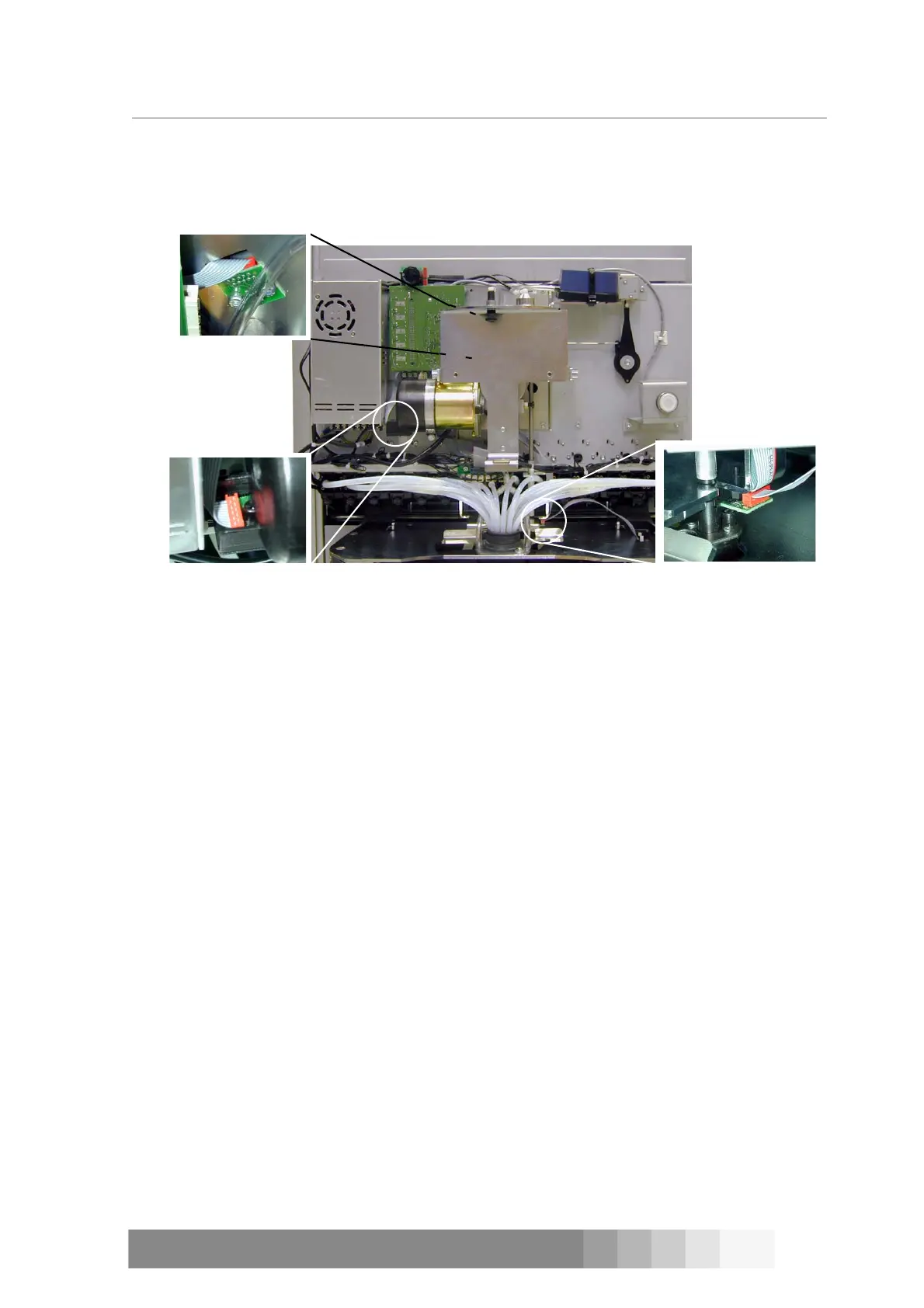
D300 has 3 sensors: pulse (PULSE), zero (ZERO) and humidifier cap (CUP). The name of
the sensor, put in brackets after the sensor’s name, is also written on the sensor board. Locations
of the sensors are shown in figure 71. In addition, COROB
TM
D300 has one pair of sensors: IR
transmitter and receiver. This infrared sensor detects if there is a paint can on the can table.
The zero sensor is behind the support of the water reservoir, see figure 12 on page 7. The sensor
is attached with two Allen screws to the motor bedstead of the dispensing motor. The pulse sensor
is attached to the casing of the dispensing motor. The sensor board is attached to the casing with a
slothead screw.
The humidifier cap sensor is attached with two crosshead screws to the adapter plate of the
nozzle.
Tools required:
• 2.5 and 3 mm Allen key
• Cross head screwdriver
Procedure
1. Switch off the COROB
TM
D300 and unplug the mains cable from the outlet.
2. Remove front casing, see instructions on page 15.
3. Open the Allen or crosshead screw(s) in the board and remove the sensor.
4. Disconnect the cable from the sensor.
5. Attach the cable to a new sensor.
6. Install the new sensor and tighten the screws.
7. Plug the mains cable to the outlet and switch on the machine.
8. Test that the sensor is working properly.
Can on can table sensor
COROB
TM
D300’s can on can table sensor is a infrared (IR) sensor that consists of two parts: trans-
mitter (B in figure 72) and receiver (A in figure 72). The sensor is on the top of the can table on
both sides of it. IR sensor is activated when the beam coming from the transmitter does not reach
the receiver. This happens when you put a paint can on the can table and lift it up against the
nozzles.
The sensors are fastened to supports that are embedded into the can table’s beams.
CUP
ZERO
PULSE
Figure 71: Locations of the sensors