3 - Maintenance instructions 33
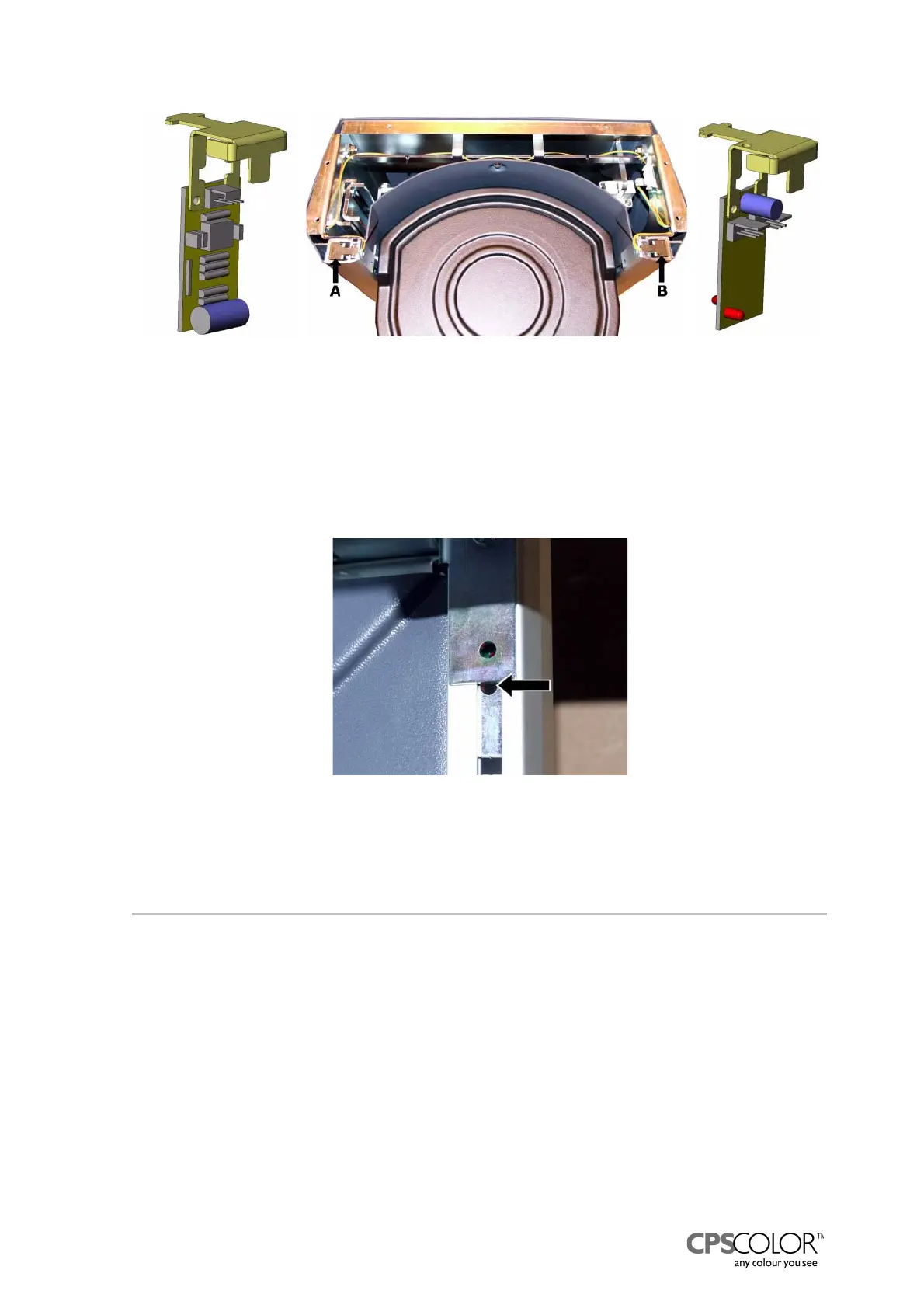
How to check the functioning of the IR sensors:
1. Station yourself beside the left guide of the can table that is beside the IR receiver.
2. Cover the holes in the guide.
3. Look over the can table to the upper part of the right-hand guide
=> through the lower hole (marked with an arrow in figure 73) you can see a red light.
3.11Replacing the processor and the connector board
The processor and the connector board of the COROB
TM
D300 is behind the front casing, in the
dispensing module, see figure 5 on page 4. The connector board is behind the processor board.
Tools required:
•Screwdriver
• 3 mm Allen key
Procedure:
1. Switch off the COROB
TM
D300 and unplug the mains cable from the outlet.
2. Remove front casing, see instructions on page 15.
3. Remove the processor board by pulling it carefully away from the connector board.
Figure 72: The can on can table -sensors, IR
transmitter B and IR receiver A, are located in upper
part of the can table assy.
Figure 73: When you cover the holes in
front of the IR receiver you can see a red
light through the lower hole (arrow) on
the transmitter’s side.