22 3 - Maintenance instructions
COROB
TM
D300
10. Open two eight-mm Allen screws from behind the can table and remove the hydraulic cylinder.
NOTE! The right screw is tightened with a locking nut.
11. Lift the cylinder beside the pump.
12. Move the hose from back to front of the pump.
13. Lift the whole unit from the can table
=> the connecting rod and compression spring are disconnected.
NOTE!: Keep the hydraulic lift unit always so that the breather hole is upwards.
3.7.1.2 INSTALLING A HYDRAULIC LIFT UNIT
Procedure
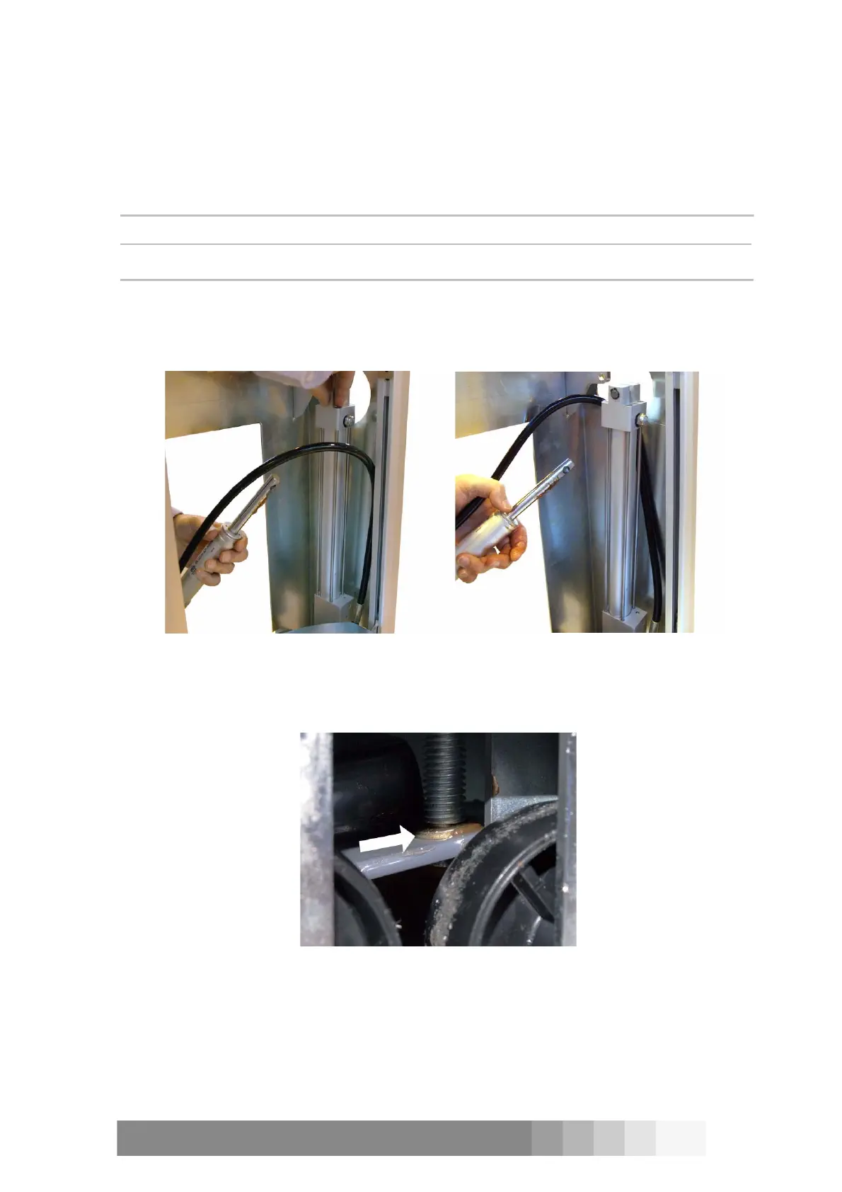
1. Place the hose in front of the pump and place the pump in position, figure 44.
2. Move the hose behind the pump, figure 45.
3. Place the connecting rod in position.
NOTE! There is a washer under the rod, see figure 46.
4. Lift up the pump a little and place the compression spring in position.
NOTE! Check that there is about 1 cm gap in the movement of the lower pedal <=> a few
millimetres gap in connecting rod.
5. Place the shaft in position in top of the pump.
6. Place the retaining rings in position.
Figure 44: Install first the hydraulic
unit’s pump in position.
Figure 45: Move the hose between the
pump and the can table.
Figure 46: There is a washer on the lever
at the bottom end of the connecting rod.