Product Overview
12 Operator’s Manual
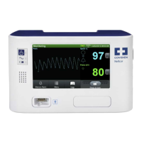
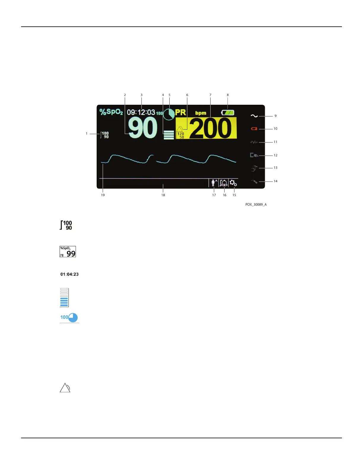
Display
Figure2-2. Display Components
1 Upper and lower alarm limits
Reflects upper and lower SpO
2 and pulse rate alarm limits.
An alarm sounds each time patient saturation or pulse rate
values violate these alarm limits.
2 SpO2 real-time value Indicates hemoglobin oxygen saturation levels. Current
upper and lower alarm limit settings appear as smaller
values to the left of the dynamic SpO
2 value.
3 Time Indicates the current time in hours, minutes, and seconds.
4 Pulse amplitude (blip bar) Indicates pulse beat and the relative (non-normalized) pulse
amplitude. As the detected pulse becomes stronger, more
bars light with each pulse.
5 SatSeconds™ icon The SatSeconds™ feature provides alarm management for
mild or brief SpO
2 limit violations. When the SatSeconds™
feature is enabled, the SatSeconds icon fills in the clockwise
direction as the SatSeconds alarm management system
detects SpO
2 readings outside of the limits setting. The Sat-
Seconds icon empties in the counterclockwise direction
when SpO
2 readings are within limits. When the SatSec-
onds icon reaches full, a medium priority alarm sounds. The
adult default setting is 100. Reference SatSeconds™ Alarm
Management Feature, p. 10-85.
6 Alarm active icon Appears, along with an alarm message, when patient
values violate an alarm limit threshold. Audible and visual
alarms occur. Reference Alarm limits menu area, p. 2-14,
for additional alarm icons.