CVC TECHNOLOGIES, INC. CVC 400 OPERATION MANUAL
7 - 6
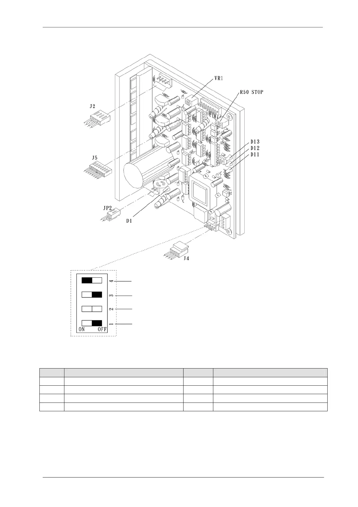
7.2.3 C7, C7-1: Stepper Motor Driver for Labeling Head
Item Description Item Description
JP2 Driver power DC 145V D1 DC 145 Power indicator
J2 Stepper motor output D11 Labeling signal indicator
J4 Power control for 5V/12V D12 Spare – for future use
J5 Signal input & energy saving mode D13 Power indicator
Dip Switch setting:
Left: Overheating protection
Spare – for future use.
a. Left: Head A stepper motor revolution switch (right hand labeling head, standard)
b. Right: 1) Head B Stepper motor revolution switch (left hand labeling head)
2) Push & Press attachment stepper motor revolution switch.
a. Left: Full step switch: 1.8˚ revolution per signal for Push & Press attachment
b. Right: Half step switch: 0.9 ˚ revolution per signal.