CVC TECHNOLOGIES, INC. CVC 400 OPERATION MANUAL
14 - 4
14.1.2 Wiring Duct
※ The input components should be matched with DC 12VG, and the output components should be matched with DC
24V or DC 12V (depending on the voltage of the component applied, motor is excluded)
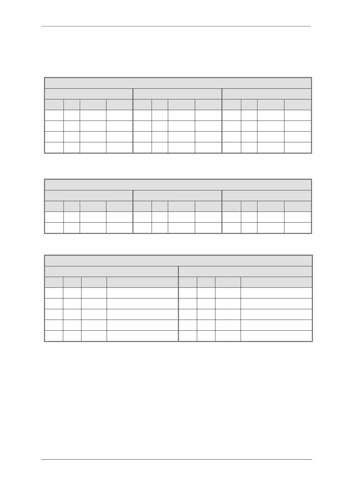
Stepper Motor Coil
Labeling Head B (Left, X1) <4P> Labeling Head A (Right, X2) <4P>
Pin No.
Color Jump No.
Definition Pin No.
Color
Jump No.
Definition
Pin No.
Color Jump No. Definition
1 RED
J29-2 A
1 RED
J29-7 A
2 YEL
J29-3 A’
2 YEL
J29-8 A’
3 ORG
J29-4 B
3 ORG
J29-9 B
4 BLU
J29-5 B’
4 BLU
J29-10 B’
DC Motor Coil
Conveyor Motor <2P> Wrapping Motor <2P> Separator Motor <2P>
Pin No.
Color Jump No.
Definition Pin No.
Color
Jump No.
Definition
Pin No.
Color Jump No. Definition
1 WHT
J30-5 M+
1 WHT
J30-7 M+
1 WHT
J30-9 M+
2 BLK
J30-6
M-
2 BLK
J30-8
M-
2 BLK
J30-10
M-
DC Motor Encoder
Conveyor Encoder <5P> Wrapping Encoder <5P>
Pin No.
Color Jump No.
Definition Pin No.
Color
Jump No.
Definition
1 BRN
J31-1 DC 12V
1 BRN
J31-1 DC 12V
2 BLU
J31-4 DC 12VG
2 BLU
J31-4 DC 12VG
3 WHT
J31-6 PH B
3 WHT
J31-8 PH B
4 GRN
J31-5 PH A
4 GRN
J31-7 PH A
5
5