SiEBE18-526 Outdoor Unit PCB Layout
Test Operation 111
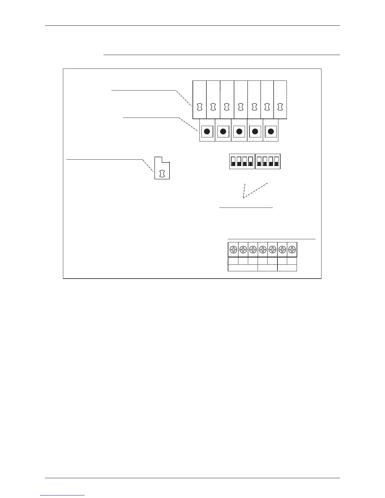
2. Outdoor Unit PCB Layout
Outdoor Unit PCB
MODE SET RETURN TESTRESET
1 2 3 4 1 2 3 4
ABC
C/H SELECTOR
TO BP UNIT
(2) Set mode display (LED)
(3) Mode setting switch
(1) Microcomputer normal monitor
(4)Local setting switch
Connection terminal for transmission use
DS1
HAP
(Q0404)
F1 F2 F1 F2
(1) Microcomputer normal monitor (LED Green)
This monitor blinks while in normal operation, and turns on or off when a malfunction occurs.
(2) Set mode display (LED Orange)
LEDs display mode according to the setting.
(3) Mode setting switch
Used to change mode.
(4) Local setting switch
Used to make local settings.
H1P H2P H3P H4P H5P H6P H7P
BS1BS2BS3 BS4BS5
DS2