Printed Circuit Board Connector Wiring Diagram SiEBE18-526
24 Printed Circuit Board Connector Wiring Diagram and Name
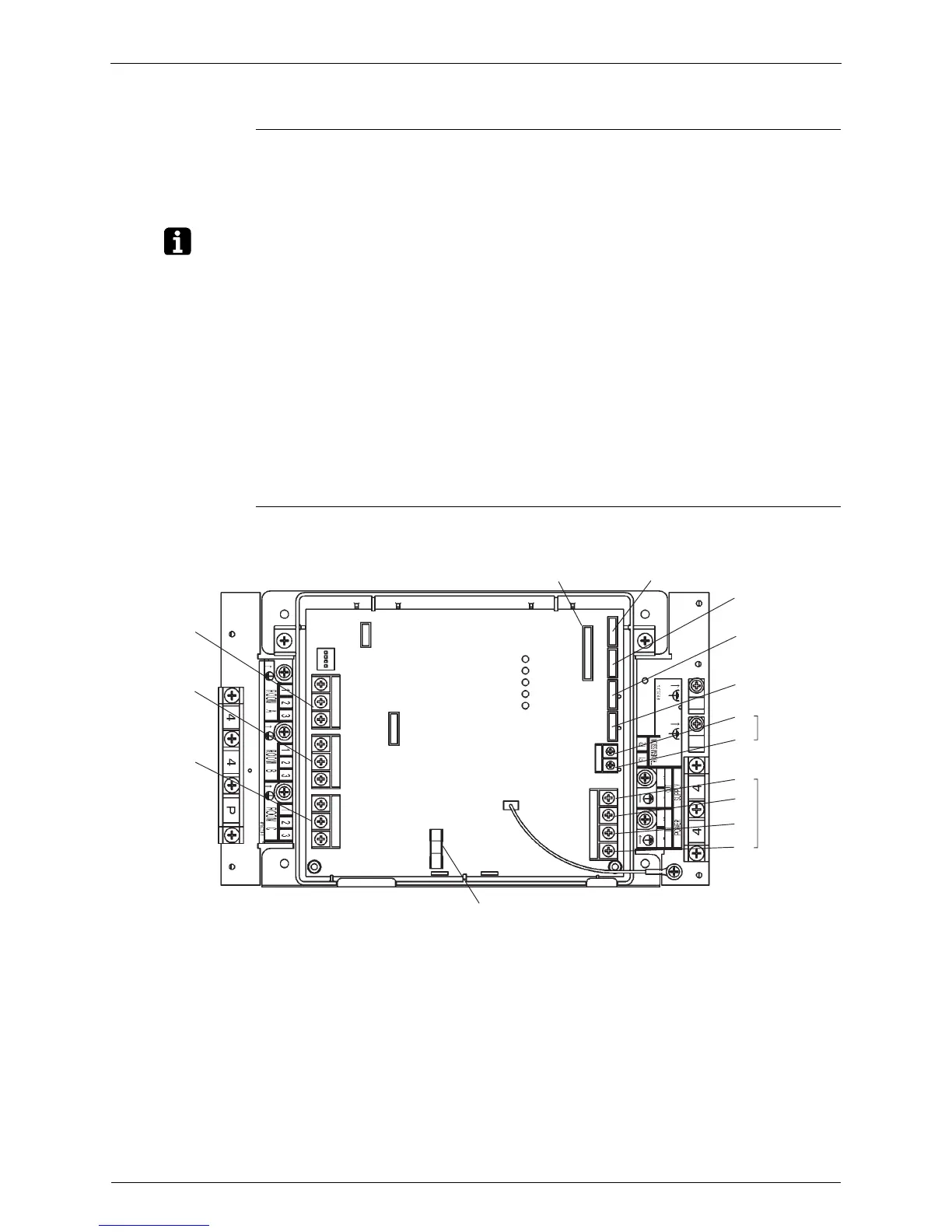
1.2 Branch Provider Unit BPMKS967A2B, B2B, A3B, B3B
Connectors
Note: Other Designations
X23A and X5M are not used for BPMKS967A2B, B2B.
PCB Detail
1) X20A Connector for Bypass Electronic Expansion Valve
2) X21A to X23A Connector for Electronic Expansion Valve to Room A, B and C
3) X90A Connector for Thermistors
1) F2U Fuse (AC250V 3.15A)
2) X3M Terminal for Inter Connecting Wire to Room A
3) X4M Terminal for Inter Connecting Wire to Room B
4) X5M Terminal for Inter Connecting Wire to Room C
5) F1, F2 (on X6M) Terminal for Transmission to Outdoor Unit or Other BP units
6) L1, N1 (on X1M) Terminal for Power Supply (230V 50Hz)
7) L2, L2 (on X1M) Terminal for Power Supply to other BP units
8) H1P(LED-A) LED for Service Monitor
9) H2P~H5P (LED 1 to 4) LED for Fault Indication
X3M
X4M
X5M
F2U
3P152439A
X22A
X21A
X20A
F2
X6M
X1M
F1
N2
L2
N1
L1
X90A X23A
H1P (LED A)
H2P (LED 1)
H3P (LED 2)
H4P (LED 3)
H5P (LED 4)
N2L2N1L1