Do you have a question about the Daikin VRV K and is the answer not in the manual?
| Category | Inverter |
|---|---|
| Refrigerant | R410A |
| Coefficient of Performance (COP) | Up to 4.5 (depending on model and configuration) |
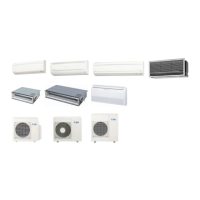
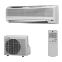
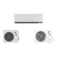
| Indoor Units Compatibility | Wall Mounted, Floor Standing |
| Operating Temperature Range (Cooling) | -5°C to 46°C |
System overview, including unit capabilities and refrigerant piping limits.
Details individual unit control, capacity variation, and flexible piping specifications.
Specifies conditions for connecting indoor and BS units to outdoor units based on capacity.
Covers refrigerant diagrams, safety devices, and operational control outlines.
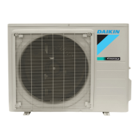
Illustrates refrigerant flow and components within the outdoor unit for various models.
Details safety devices and functional parts with their corresponding setting values.
Diagrams show refrigerant path during cooling, heating, and simultaneous operations.
Explains PI control for compressors, heat exchangers, and motorized valves.
Covers restart safety timers and soft start procedures for compressor protection.
Describes the process for equalizing oil levels between twin compressors.
Details the procedure for collecting and returning refrigeration oil from the piping.
Explains conditions and methods for melting frost on outdoor heat exchangers.
Describes control to balance pressure during BS unit solenoid switching.
Limits compressor capacity to prevent abnormal noise during equalizing operations.
Explains solenoid valve switching based on indoor unit operating conditions.
Details pump-down operation to discharge refrigerant from the low-pressure side.
Covers controls for high pressure, low pressure, discharge pipe temp., and inverter current.
Describes reducing outdoor unit noise by lowering fan and compressor speeds.
Explains demand operation modes for controlling power consumption.
Details the 20-stage capacity control for inverter and standard compressors.
Allows adjustment of target Te/Tc values for compressor capacity control.
Details the U0 alarm for severe gas depletion, indicated during operation.
Explains drain pump control via ON/OFF buttons and float switch operation.
Allows air direction adjustment to prevent ceiling dirt on cassette units.
Describes temperature control using remote and indoor unit sensors.
Explains freeze prevention operation when indoor heat exchanger temperature drops.
Covers procedures for initial power-on, setup, and unit extension/replacement.
Details initial operation, LED indicators, and automatic setting procedures.
Diagram and identification of components on the outdoor unit PC board.
Explains navigation of Setting Mode 1, Setting Mode 2, and Monitor Mode.
Describes separating compressor start timing to prevent over-current.
Explains use of external control adaptor for demand and low noise control.
Details three methods for setting cool/heat modes for BS unit systems.
Describes connecting external input to lower operating noise and save power.
Explains connecting external input for controlling compressor operation for reduced power.
Provides procedure to check transmission wiring between indoor and outdoor units.
Covers field settings for indoor units using wired or wireless remote controllers.
Explains setting group numbers for centralized control using remote controllers.
Details setting one remote controller as master for operation mode selection.
Explains remote controller self-diagnosis for identifying malfunctions.
Describes using the inspection/test button for checking unit status and codes.
Guides on entering and operating the remote controller's service mode.
Lists malfunction codes, their contents, and fan operation status.
Table correlating malfunction codes with descriptions and page references.
Categorizes failures for inverter systems and optional controllers.
Detailed troubleshooting for various indoor and outdoor unit malfunctions.
Troubleshooting steps for 'A0' error related to external protection devices.
Steps for diagnosing and fixing 'A1' error indicating PC board defect.
Troubleshooting for 'A3' error related to drain level control system.
Diagnosing and fixing 'A6' error for fan motor lock or overload.
Troubleshooting steps for 'A7' error related to swing flap motor.
Troubleshooting for 'A9' error concerning electronic expansion valve.
Resolving 'AF' error indicating drain level is above the limit.
Troubleshooting for 'AJ' error related to capacity determination device.
Diagnosing and fixing 'C4' error for faulty liquid pipe thermistor.
Troubleshooting for 'C5' error related to gas pipe thermistor.
Troubleshooting for 'C9' error concerning air inlet thermistor.
Resolving 'CJ' error for faulty thermostat sensor in remote controller.
Troubleshooting for 'E0' error indicating actuation of outdoor unit safety device.
Diagnosing and fixing 'E1' error indicating outdoor unit PC board defect.
Troubleshooting for 'E3' error related to high pressure switch.
Details troubleshooting for 'E4' error indicating actuation of low pressure sensor.
Troubleshooting for 'E9' error concerning electronic expansion valve.
Guides on resolving 'F3' error related to abnormal discharge pipe temperature.
Troubleshooting for 'H9' error concerning outdoor air thermistor.
Troubleshooting for 'J3' error related to discharge pipe thermistor.
Guides on diagnosing and fixing 'J5' error for faulty suction pipe thermistor.
Troubleshooting for 'J6' error related to heat exchanger thermistor.
Troubleshooting for 'JA' error concerning discharge pipe pressure sensor.
Guides on resolving 'JC' error related to suction pipe pressure sensor.
Troubleshooting for 'JH' error concerning oil temperature thermistor.
Troubleshooting for 'U0' error related to low pressure drop.
Diagnosing and fixing 'U1' errors for negative or open power supply phases.
Troubleshooting for 'U4' error concerning transmission issues between indoor units.
Troubleshooting for 'U5' error related to transmission between remote and indoor units.
Guides on resolving 'U7' error concerning transmission issues between outdoor units.
Troubleshooting for 'U8' error related to transmission between main and sub remote controllers.
Troubleshooting for 'U9' error concerning transmission between indoor/outdoor units in the same system.
Guides on resolving 'UA' error indicating an excessive number of connected indoor units.
Troubleshooting for 'UC' error related to address duplication of the central remote controller.
Troubleshooting for 'UF' error indicating an unset refrigerant system or incorrect wiring/piping.
Guides on resolving 'UH' error concerning system malfunction or undefined refrigerant system address.
Provides characteristic data for thermistors and pressure sensors.
Lists resistance values for thermistors at various temperature points.
Shows the relationship between pressure sensor output voltage and detected pressure.
Details replacing power transistors and diode modules on the inverter PC board.
Offers precautions for PC board replacement and remote controller mode numbers.
Illustrates common wiring errors and their resulting operational issues.