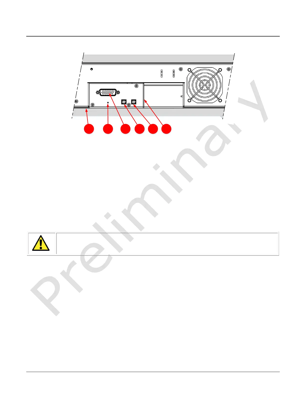
Figure 6. Module I / O Connectors
Camera I / O Connectors
1) Factory use only
2) Data and control connectors – two LC Fiber pairs
3) LED status indicators
4) Power and GPIO connectors: +24 V DC, two I/P, four O/P, 26 pin HD D-Sub connector
5) LED array#1 power. Note: Is being changed
6) LED array#2 power. Note: Is being changed
Powering the Module
• The 24V supply must be isolated from frame ground of the power supply to
prevent potential ground loop issues.
• Before connecting power to the module, verify the power supply voltage.
• Apply the +24 V. Incorrect voltages may damage the camera.
• There will be no current draw and the unit will not turn on below 20.4V
• Protect each module section with a 5 amp slow-blow fuse or circuit breaker between the
power supply and the module.
• Do not use the shield on a multi-conductor cable for ground.
• Keep power leads as short as possible in order to reduce voltage drop.
• Use high quality supplies in order to minimize noise.