52 • Appendix A: GenICam Commands Linea HS Series Camera User's Manual
Digital IO Control Category
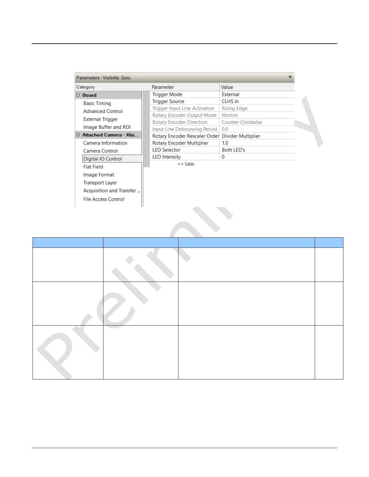
The camera’s Digital IO Control category is used to configure the cameras GPIO pins.
Figure 17 Digital I/O Control Panel
Digital IO Control Feature Descriptions
Determines the source of trigger to the camera.
Line rate is controlled with AcquisitionLineRate
feature.
Trigger comes from CLHS (frame grabber) or GPIO.
Determines the source of external trigger.
Source of trigger is from the frame grabber over
CLHS.
Trigger source is from the two shaft encoder inputs.
Trigger source is from Line 1 of the GPIO connector.
Trigger Input Line
ActivationEdge
Determines which edge of a input trigger will
activate on
The trigger is considered valid on the rising edge of
the line source signal (after any processing by the
line inverter module).
The trigger is considered valid on the falling edge.
The trigger is considered valid on any edge.