EasyManua.ls Logo

Dalsa A CIS Series - Power and GPIO Connections; Figure 7: 26-Pin High Density D-Sub Pin Numbering

Default Icon
75 pages
Print Icon
To Next Page IconTo Next Page
To Previous Page IconTo Previous Page
Loading...
20 AxCIS Series Camera Features Linea HS Series Camera User's Manual
Power and GPIO Connections
The module uses a single 26-pin high density D-Sub male connector for power, trigger and strobe
signals.
26-pin high density D-Sub Signal Details
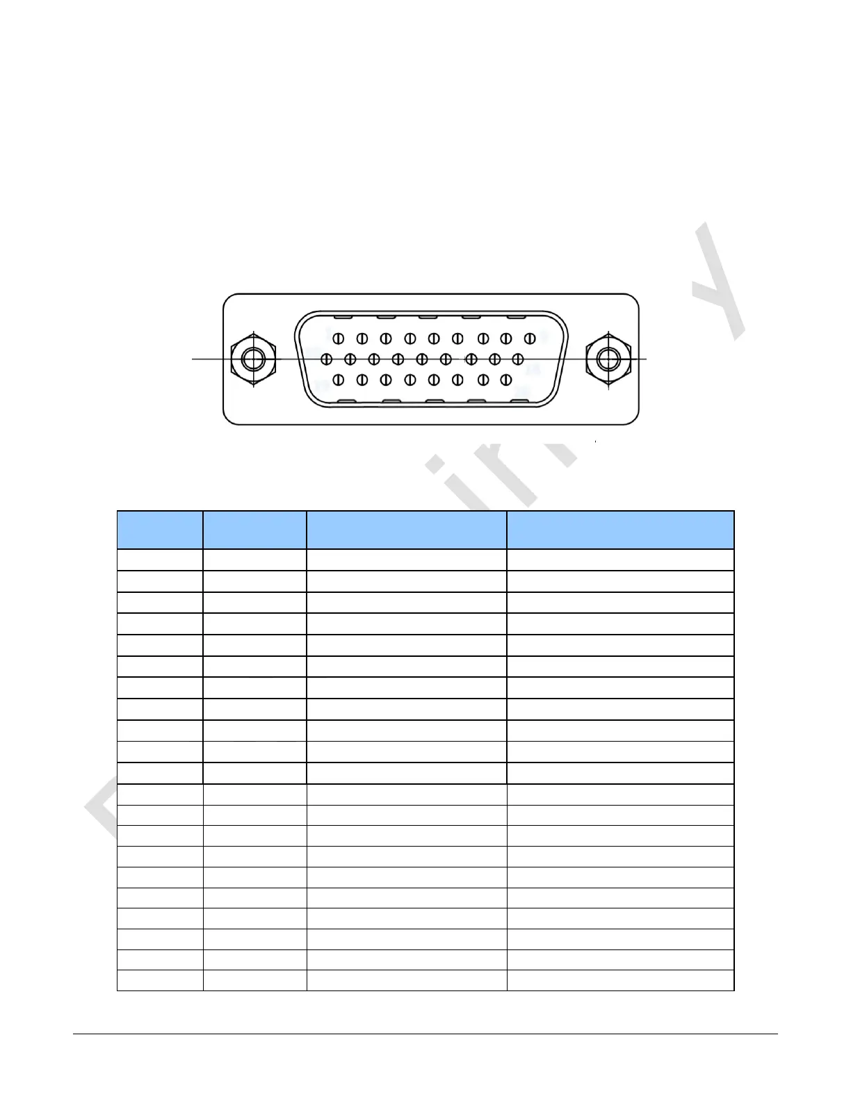
The following figure shows the pinout identification when looking at the module’s 26-pin male HD
D-Sub connector. The table below lists the I/O signal connections.
1
9
10
18
19
26
Figure 7: 26-pin high density D-Sub Pin Numbering
Table 5: 12-pin Hirose Pin Assignment
Pin Number
Signal Input /
Output
Signal Details
Notes
1
Input
Encoder Phase A+
RS422 Signal
2
Input
Encoder Phase A-
RS422 Signal
3
Input
Encoder Phase B+
RS422 Signal
4
Input
Encoder Phase B-
RS422 Signal
5
+24V Power
6
+24V Power
7
Reserved. Do not connect
8
Power Ground
9
Power Ground
10
Output
Line#1+
RS422 Signal
11
Output
Line#1-
RS422 Signal
12
Output
Line#2+
RS422 Signal
13
Output
Line#2-
RS422 Signal
14
+24V Power
15
+24V Power
16
Reserved. Do not connect
17
Power Ground
18
Power Ground
19
Output
Line#3+
RS422 Signal
20
Output
Line#3-
RS422 Signal
21
Output
Line#4+
RS422 Signal

Table of Contents