54 • Appendix A: GenICam Commands Linea HS Series Camera User's Manual
Flat Field Category
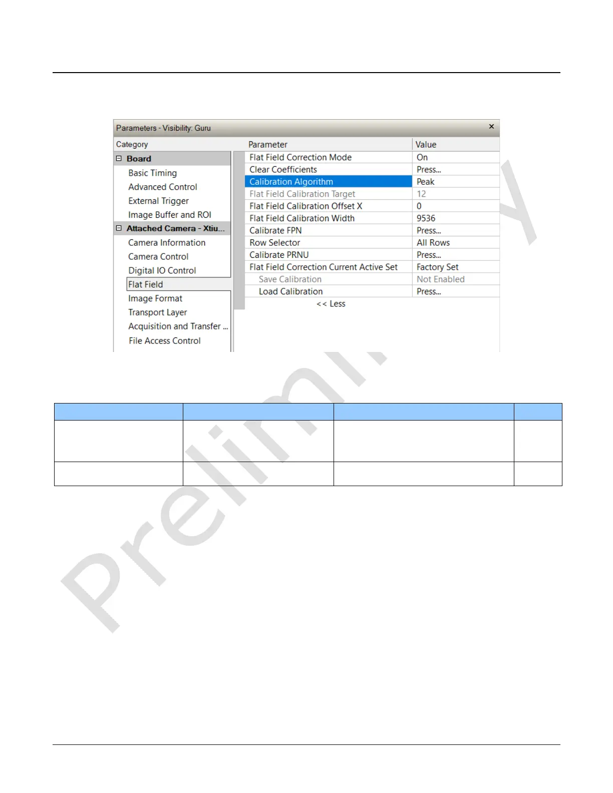
The Flat Field controls, as shown by CamExpert, group parameters used to control the FPN and
PRNU calibration process.
Figure 18: Flat Field Panel
Flat Field Control Feature Description