29 of 132
M-SV-001-EN Rev.E
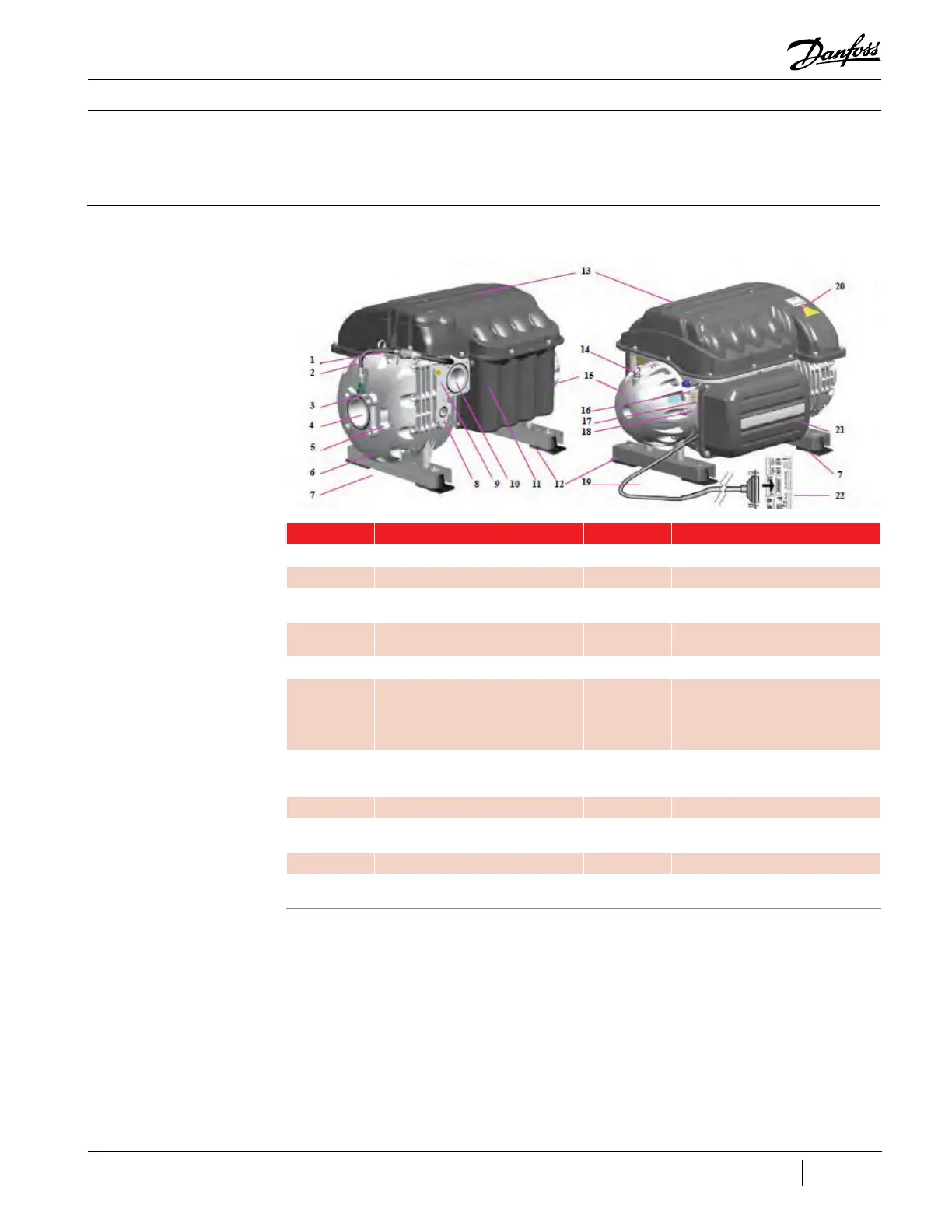
Figure 19 - Compressor
Components Identification
(Covers On)
Compressor Components
This section provides compressor component
locations and functional descriptions, verification
and troubleshooting methods, cable connection
identification, and steps necessary to replace a
component.
This section identifies the major parts of the
compressor.
3.1 Component
Identification
Table 4 - Compressor
Component Identification
(Covers On)
No. Component No. Component
1 Lift Anchor (Front) 12 Rear Support Base
2 Cable Harness (Sensor) 13 Top Access Cover
3
Suction Pressure/
Temperature Sensor
14 Lift Anchor (Rear)
4
Inlet Guide Vanes (IGV)
Suction Port
15 End Bell
5 IGV Position Indicator 16 Motor-Cooling Connection
6 IGV Housing 17
Motor-Cooling (TT300/TG230) and
Power Electronics Cooling (TT350/
TT400/TT500/TT700/TG310/TG390/
TG520) Access Port #1 (NOTE: TT300/
TG230 have only one access port)
7 Front Support Base 18
Motor-Cooling Access Port #2
(TT350/TT400/TT500/TT700/TG310/
TG390/TG520 Only)
8 Economizer Port 19 Compressor I/O Board Cable
9
Optional Pressure
Regulating Port
20 Mains Input Access Cover
10 Discharge Port 21 Service Side Access Cover
11
Capacitor Side Access
Cover
22 Compressor I/O Board

 Loading...


