66 of 132
M-SV-001-EN Rev.E
Compressor Components
3.10.2.2 Backplane
Verification
1. Remove the Service Side Cover.
2. With main power on, using a multimeter set for
DC voltage measurements, place the multimeter
leads in the Backplane test points as defined in
Table 12 (Backplane Test Point Values). See Figure
60 (Backplane Connections and Test Points).
The results should be within the voltage range
specified in the table.
3. Isolate compressor power.
4. Unplug connectors J4 and J24 from the
Backplane.
5. Using a multimeter set for resistance
measurements, place the multimeter leads in
the Backplane test points as defined in Table
12 (Backplane Test Point Values). See Figure 60
(Backplane Connections and Test Points). The
results should be greater than the resistance
specified in the table.
6. If one of the test points does not output the
expected voltage and the HV+ and +24V test
points output the correct voltage, remove the
Serial Driver, BMCC, and PWM.
7. Plug connectors J4 and J24 to the Backplane.
8. Repeat Step 2. If the voltages are as expected,
the Backplane is functioning correctly.
NOTE
The test-point LEDs are ON if any voltage is present. The test points must be measured to determine the actual voltage.
• • • CAUTION • • •
The Inverter cable must be connected to the Backplane, J6, if the BMCC is removed and power is applied to the compressor.
Table 12 - Backplane Test
Point Values
Test Point Test Point Reference DC Voltage Range Minimum Resistance
HV+ HV- 220 to 280 250Ω
+17HV HV- 16.5 to 17.85 28Ω
+24V 0V 22 to 26 9Ω
+15V 0V 14.75 to 15.25 20Ω
+15V 0V -14.75 to -15.25 150Ω
+5V 0V 4.75 to 5.25 8Ω
3.10.3 Removal and
Installation
1. Isolate compressor power and wait for the
Backplane LEDs to go out.
2. Remove the J4 and J24 connectors from the
Backplane.
3. Remove the Bearing PWM Amplifier, Serial
Driver, and BMCC.
4. Disconnect all remaining connectors from the
Backplane. See Figure 60 (Backplane Connections
and Test Points).
5. Remove the Inverter ground screw from top
right of the Backplane to release the Inverter
cable ground ring.
6. Replace the Inverter ground screw.
7. Remove the fasteners at the top of the
Backplane frame and the frame ground screw
at the bottom right that secures the Backplane
to the housing. See Figure 62 (Removing the
Backplane).
3.10.3.1 Backplane
Removal
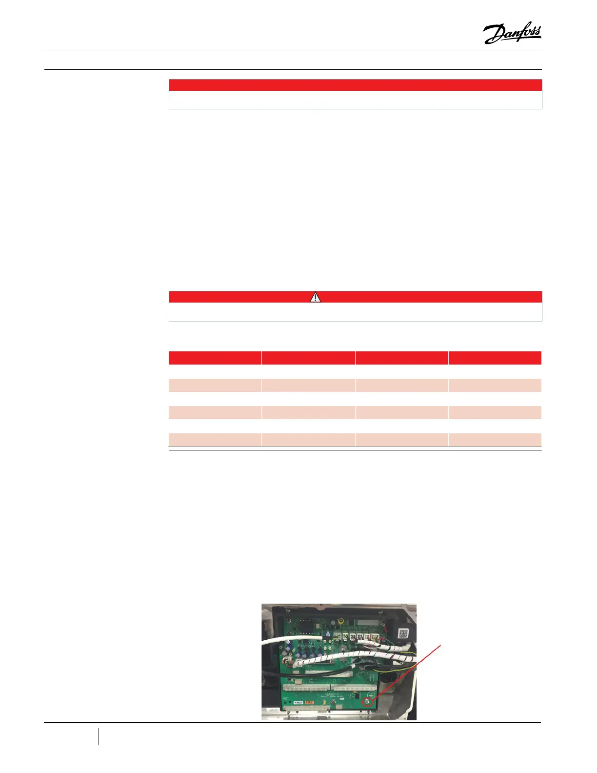
Figure 62 - Removing the
Backplane
Frame Ground
Screw

 Loading...


