53 of 132
M-SV-001-EN Rev.E
Compressor Components
3.7.3 Verification
3.7.3.1 Inverter
Verification
This procedure only verifies the Inverter diodes.
The Inverter Control Board cannot be verified in
the field. A faulty Inverter may also appear as an
“Inverter Error Signal Active” fault.
1. Isolate the compressor power as described
in the “Electrical Isolation of the Compressor”
section of this manual.
2. Remove the Soft Start Module.
3. Remove the DC Capacitor Assembly.
4. Remove the copper standoffs and fasteners
connecting the motor bus bars to the Inverter
Module.
5. Disconnect the Inverter ribbon cable from the
Inverter Module.
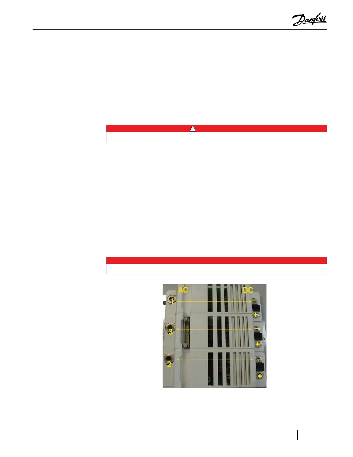
6. Using a multimeter set for diode
measurements, place the red (+) multimeter
lead on the phase 1 AC terminal and the black
(-) multimeter lead on the DC+ terminal. The
measured value should be 0.275V – 0.4V. See
Figure 44 (Inverter Connections).
7. Keeping the red (+) multimeter lead on
the phase 1 AC terminal, place the black (-)
multimeter lead on the DC- terminal. The
measured value should be open. See Figure 44
(Inverter Connections).
8. Place the black (-) multimeter lead on the
phase 1 AC terminal and the red (+) multimeter
lead on the DC+ terminal and record the results.
The measured value should be open. See Figure
44 (Inverter Connections).
9. Keeping the black (-) multimeter lead on the
phase 1 AC terminal, place the red (+) multimeter
lead on the DC- terminal. The measured value
should be 0.275V – 0.4V. See Figure 44 (Inverter
Connections).
10. Repeat Steps 6 through 9 for the remaining
Inverter phases. See Figure 44 (Inverter
Connections).
• • • CAUTION • • •
A faulty Inverter module could be the result of a faulty Stator. If an Inverter module is found to be faulty, the Stator must be
verified as well.
NOTE
These values can vary depending on the meter being used. The main idea is that the values be consistent between phases.
Figure 44 - Inverter
Connections (TT300/TG230)

 Loading...


