65 of 132
M-SV-001-EN Rev.E
Compressor Components
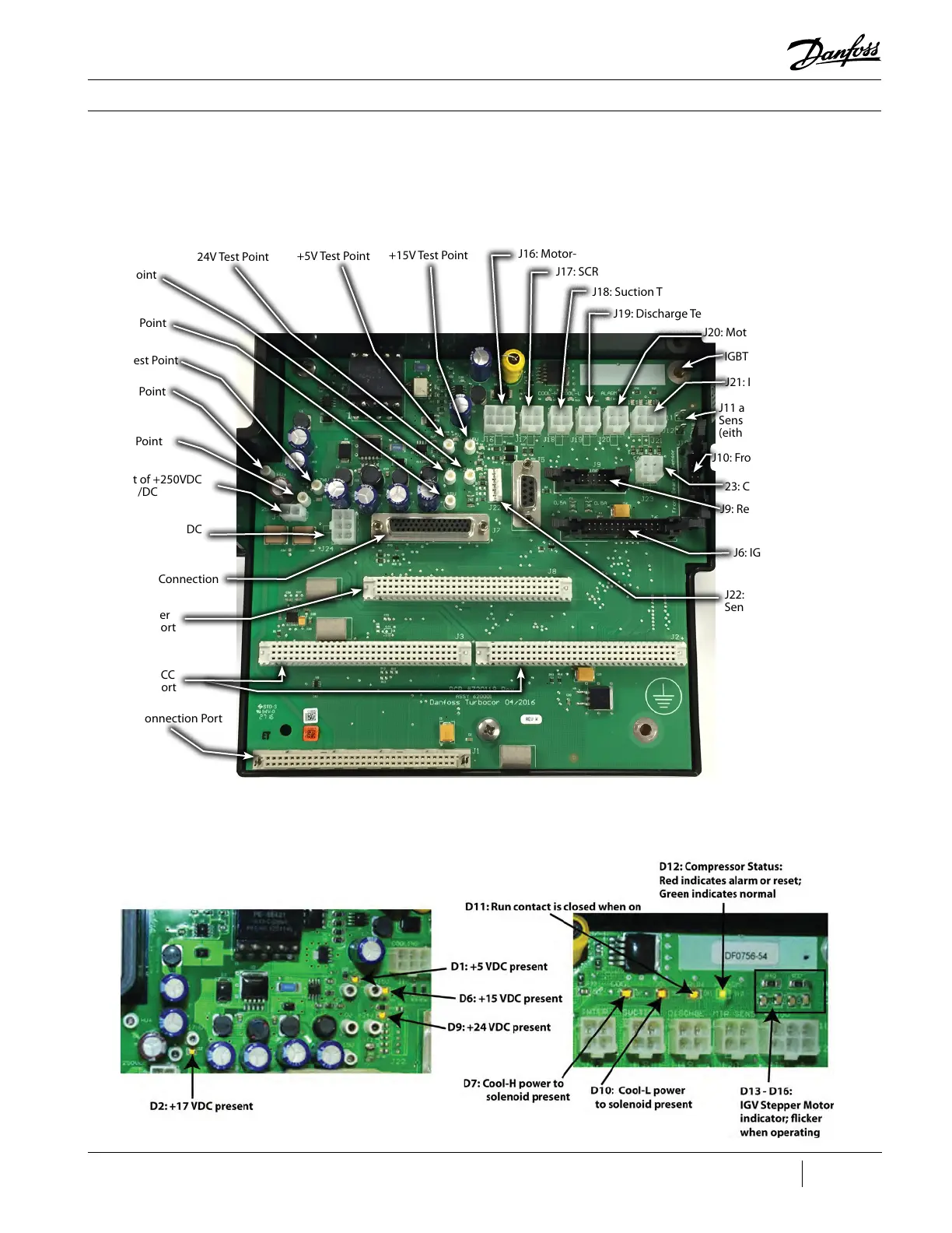
Figure 60 - Backplane
Connections and Test Points
Figure 61 - LED Locations
3.10.2 Backplane
Connections and Test
Points
3.10.2.1 LED
Locations
The Backplane connections and test points are
indicated in Figure 60 (Backplane Connections
and Test Points).
The LED locations are indicated in Figure 52
(LED Locations).
J4: Input of +250VDC
From DC/DC
J24: Input of +24VDC
from DC/DC
J7: I/O Cable Connection
J8: Serial Driver
Connection Port
J2 and J3: BMCC
Connection Port
J1: PWM Connection Port
0V Test Point
-15V Test Point
24V Test Point
+5V Test Point
+15V Test Point
J16: Motor-Cooling Solenoids Control Port
J17: SCR Temperature Sensor Port
J18: Suction Temperature/Pressure Sensor Port
J19: Discharge Temperature/Pressure Sensor Port
IGBT Ground Screw
J20: Motor-Winding Sensor Port
J11 and J12: Rear Bearing
Sensor Cable to Ground
(either may be used)
J21: IGV Motor Control Port
J10: Front Bearing Sensor Input
J9: Rear Bearing Sensor Input
J6: IGBT Connection Port
+17HV Test Point
HV+ Test Point
HV- Test Point
23: Cavity Sensor Input
J22: Soft Start Temperature
Sensor

 Loading...


