87 of 132
M-SV-001-EN Rev.E
Compressor Components
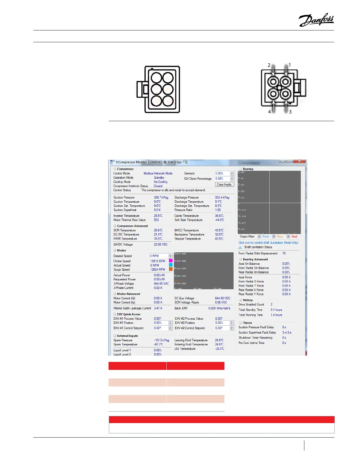
Figure 86 - Compressor
Monitor Tool
3.17.3.2 Bearing
Current Verification
1. Connect to the compressor using the SMT.
2. Open the Compressor Monitor tool. See Figure
86 (Compressor Monitor Tool).
3. In the bearing section, verify the bearing
amperages displayed are within the range
defined in Table 15 (Bearing Amperage Ranges)
during compressor operation.
Table 15 - Bearing Amperage
Ranges
Bearing Position Force Range
Axial Force -1 to 1 Amp
Front X Force -1 to 1 Amp
Front Y Force -1 to 1 Amp
Rear X Force -1 to 1 Amp
Rear Y Force -1 to 1 Amp
NOTE
The above amperage ranges are a general observation. It is possible to operate outside this range.
Figure 85 - Front and Rear
Bearing Feed Throughs with
Molex Connectors
Rear
Front
2
3
1
4
1 6
2 5
3 4

 Loading...


