45 of 132
M-SV-001-EN Rev.E
Compressor Components
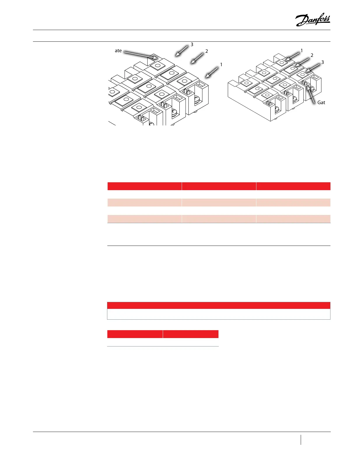
Figure 36 - Silicon-Controlled
Rectifier Terminals
5. All other terminals should read infinity or open
in both directions (polarity). See Table 10 (SCR
Diode Values).
Table 10 - SCR Diode Values
Positive (+) Lead Negative (-) Lead Expected Result
1 2 Infinity or Open
1 3 Infinity or Open
2 1 Infinity or Open
3 1 0.3V and 0.45V
3.5.3.2 Gates Verification 1. Isolate the compressor power as described
in the “Electrical Isolation of the Compressor”
section of this manual.
2. Using needle-nose pliers, carefully remove the
SCR gate cable harness from the SCRs.
3. Using a multimeter set for resistance
measurements, place the leads on the two gate
terminals. The value should be between 1 to 25Ω.
4. Reverse the leads. The measured value should
be the same.
NOTE
These values can vary depending on the meter being used. It is important that the values be consistent between SCRs.
Table 11 - SCR Gate
Resistance Ranges
SCR Model Range
All models 1 - 25Ω
TT300/TG230
Gate
Gate
3
3
2
2
1
1
TT350, TT400, TT500, TT700, TG310, TG390, and TT520

 Loading...


