88 of 132
M-SV-001-EN Rev.E
Compressor Components
3.18 Bearing Sensors
3.18.1 Function
Bearing sensors feed back real-time shaft orbit
information to the bearing control loop. See
Figure 74 (Bearing Control Signal Flow).
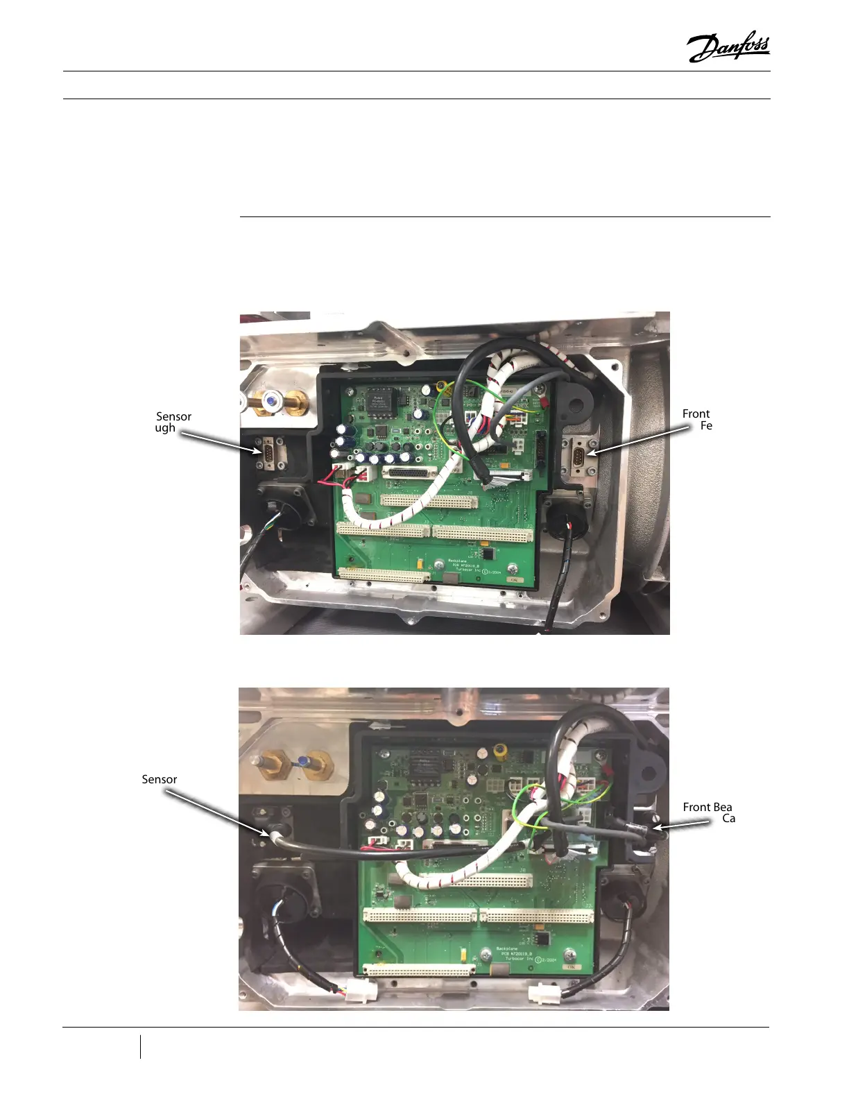
3.18.2 Connections The Bearing Sensors are connected internally to
the Bearing Sensor feed throughs located above
the front and rear bearing power feed throughs.
See Figure 87 (Bearing Sensor Feed Throughs).
The bearing sensor feed throughs are connected
to the bearing sensor cables which connect to J9
and J10 on the Backplane. See Figure 88 (Bearing
Sensor Cables).
Figure 87 - Bearing Sensor
Feed Throughs
Figure 88 - Bearing Sensor
Cables
Rear Bearing Sensor
Feed Through
Rear Bearing Sensor
Cable
Front Bearing Sensor
Feed Through
Front Bearing Sensor
Cable

 Loading...


