75 of 132
M-SV-001-EN Rev.E
Compressor Components
3. Reinstall the Serial Driver.
4. Reinstall Service Side Cover.
5. Reapply power to compressor.
6. If a BMCC that is not original to the compressor
is installed, a calibration must be completed and
saved to the EEPROM to match the BMCC to the
compressor. See Section 4.3 (Bearing Calibration).
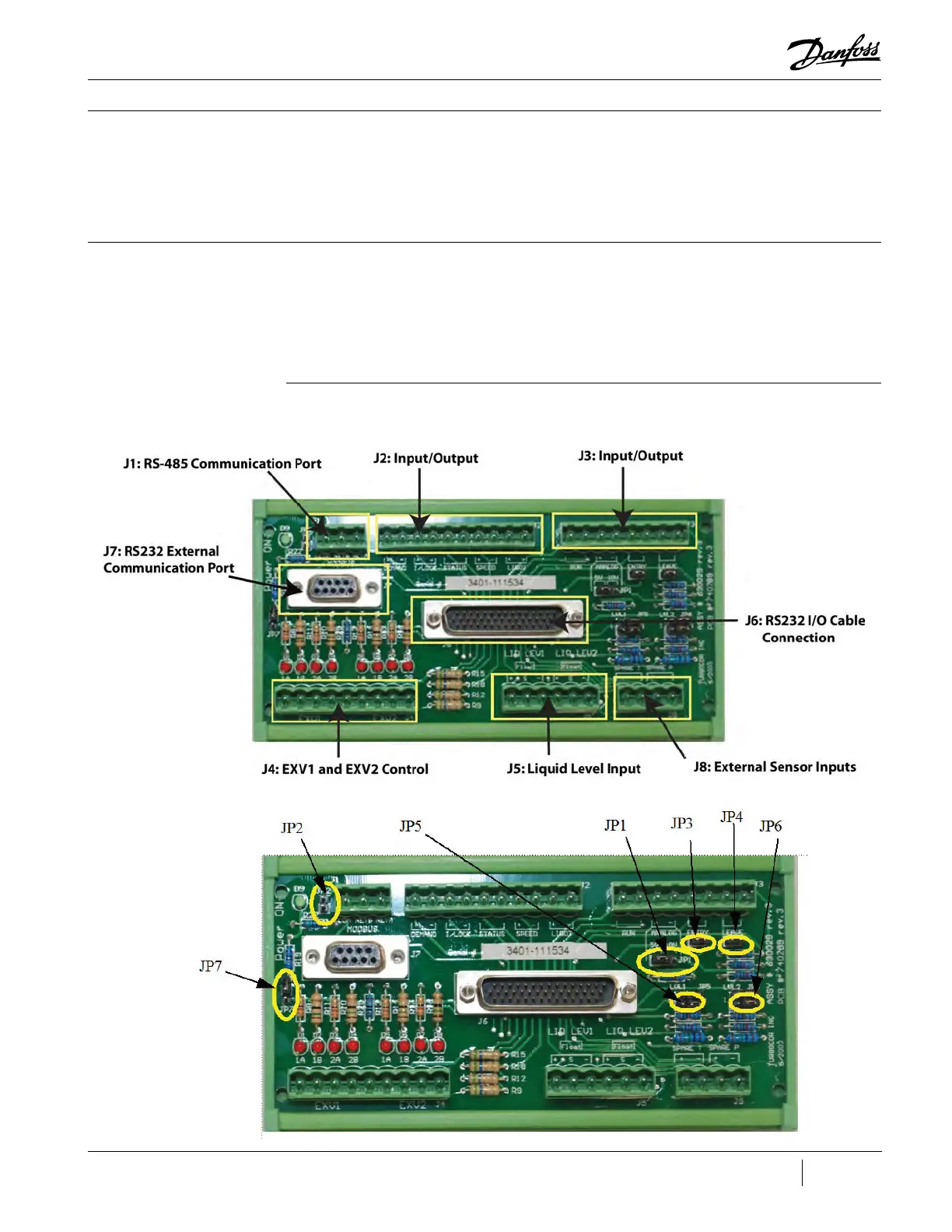
Figure 71 - Compressor
Interface Module Ports
Figure 72 - Compressor
Interface Module Jumper
Locations
3.15 Compressor
Interface Module
3.15.1 Function
3.15.2 Connections
The Compressor Interface Module (CIM),
also referred to as the Compressor I/O Board,
allows the user to control the compressor and
allows the compressor to return status and
sensor information to the user. See Figure 71
(Compressor Interface Module Ports) and Figure
72 (Compressor Interface Module Jumper
Locations) for I/O board connection locations.

 Loading...


