56 of 132
M-SV-001-EN Rev.E
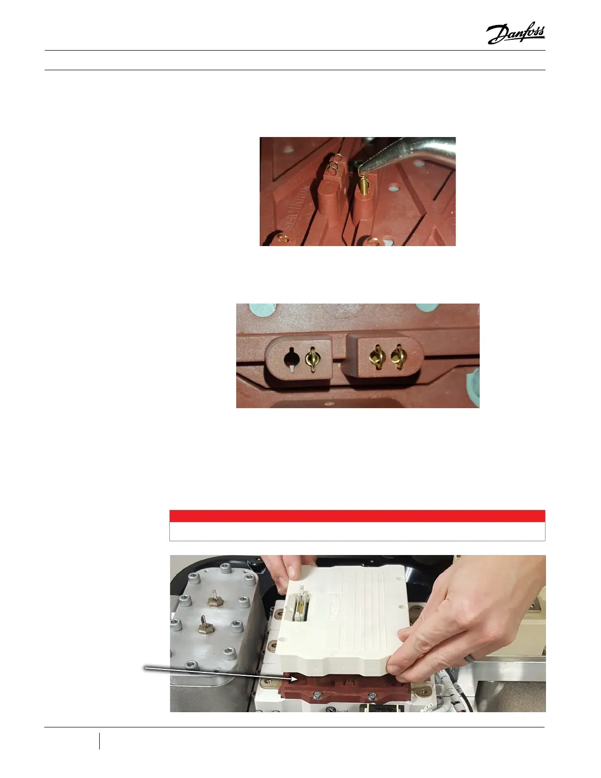
Figure 49 - Spring Pin
Removal
4. Insert the new pins carefully and verify they
line up in the notches. Refer to Figure 50 (Seated
Spring Pins).
Figure 50 - Seated Spring
Pins
5. For proper alignment, insert two (2) of the
screws in opposite corners of the Driver Board.
6. Align the new Driver Board over the IGBT
module with the connector towards motor stator
output bus bar (the shape of Driver Board must
be aligned with IGBT Press Plate shape).
7. Insert the screws into the corresponding Press
Plate holes.
8. Moving in a vertical direction only, lower the
Driver Board down on the IGBT module, do not
allow for any lateral movement.
• • • CAUTION • • •
Any lateral movement may damage the spring pins.
Figure 51 - Driver Board
Placement
3. Discard the defective spring pins and inspect
the IGBT for any foreign objects.
Press Plate

 Loading...


