39 of 132
M-SV-001-EN Rev.E
Compressor Components
5. If the meter does not show any reading, it
is possible that there is no power from the AC
source. Ensure the AC power source is turned ON
and try again. If there is no power on the load
side of the fuses (TT300/TG230 only), isolate the
power and check the fuses.
6. If the measured values correspond to the
specified values for all phases, the AC input
voltage is OK.
3.3.4.1 Terminal Block
Removal (TT350/TT400/
TT500/TT700/TG310/
TG390/TG520)
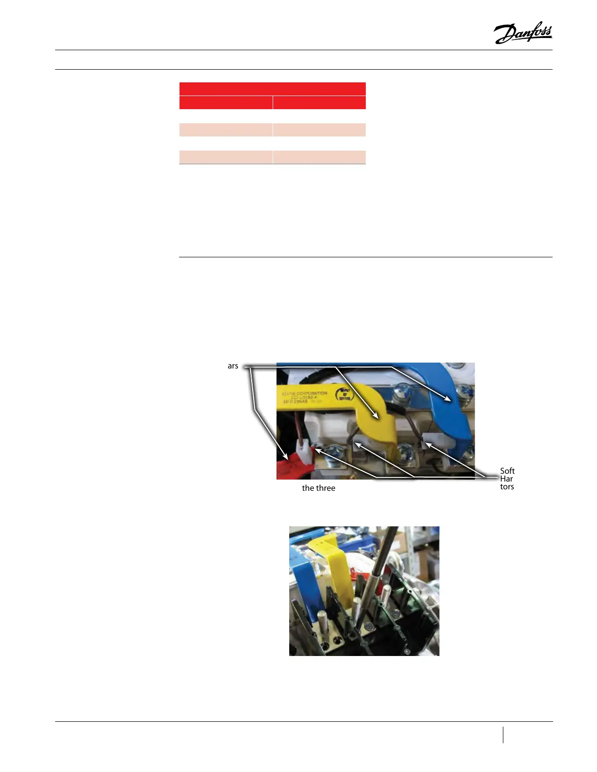
Figure 28 - Terminal Block
Bus Bars (TT350/TT400/
TT500/TT700/TG310/TG390/
TG520)
Figure 29 - Terminal Block
Bus Bars (TT350/TT400/
TT500/TT700/TG310/TG390/
TG520)
Table 9 - Expected AC
Voltage Range
AC Input
Nameplate Voltage Acceptable Voltage Range
575VAC 518 to 632VAC
460VAC 414 to 506VAC
400VAC 360 to 440VAC
380VAC 342 to 418VAC
1. Isolate the compressor power as described
in the “Electrical Isolation of the Compressor”
section of this manual.
2. Disconnect the main input cables from
terminal blocks.
3. Disconnect the three connectors of the Soft
Start Cable Harness from the bus bars.
4. Remove the screws that secure the three
terminal block bus bars to the SCR diodes. See
Figure 28 (Terminal Block Bus Bars).
5. Remove the screws that secure the three
terminal block bus bars to the terminal block. See
Figure 29 (Terminal Block Bus Bars).
6. Lift and remove the terminal block bus bars.
7. Remove the screws that secure the terminal
block to the casting.
8. Remove the terminal block.
3.3.4 Removal and
Installation
AC Bus Bars
Soft Start Cable
Harness Connec-
tors

 Loading...


