69 of 132
M-SV-001-EN Rev.E
Compressor Components
3.12.3 Verification
3.12.3.1 Resistance
Measurement of Cooling
Solenoid Actuator Coils
1. Isolate compressor power.
2. Remove the Service Side Cover.
3. Disconnect the Motor-Cooling Solenoid
Connector (J16) from the Backplane.
4. Set the multimeter for resistance
measurement.
5. Observe the voltage and power specification
indicated on the side of the Motor-Cooling
Solenoids. From Table 13 (Solenoid Actuator Coil
Resistance Ranges), find the expected resistance
for the left and right Motor-Cooling Solenoids.
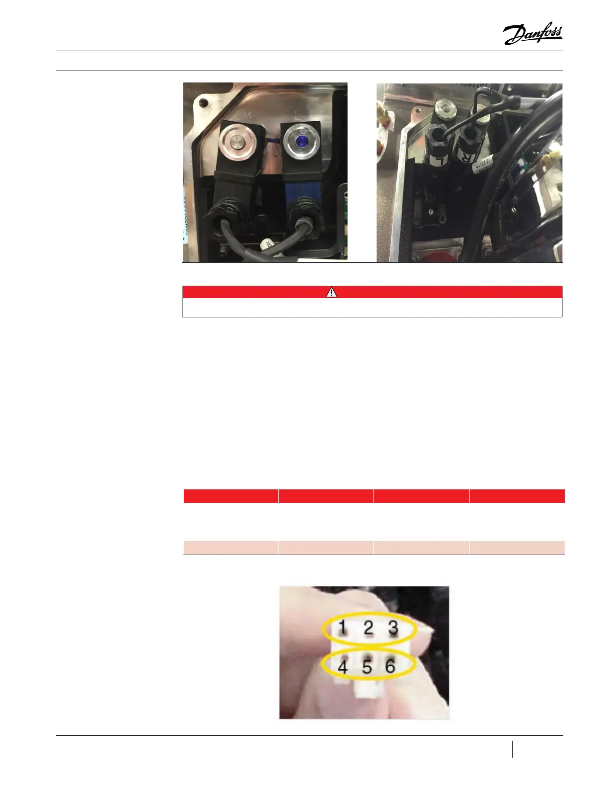
6. To measure the resistance across the left
Motor-Cooling Solenoid, place the meter probes
at Pins 1 and 3 of the cable connector. See Figure
65 (Motor Cooling Solenoid Cable Connector).
7. To measure the resistance across the right
Motor-Cooling Solenoid, place the meter probes
at Pins 5 and 6 of the cable connector. See Figure
65 (Motor Cooling Solenoid Cable Connector).
Figure 64 - Motor Cooling
Solenoid Actuators
Table 13 - Solenoid Actuator
Coil Resistance Ranges
• • • CAUTION • • •
When actuator coils are removed from the solenoids, they must be replaced in the same location. Incorrect installation can result
in damage to compressor components.
Model Voltage Power Resistance
TT300 starting at
142035030, TT350, TT500,
TT700, TG230, TG310,
TG390, & TG520
24V 9.3W 56.25Ω – 68.75Ω
TT300 prior to 142035030 24V 4.8W 108Ω – 132Ω
Figure 65 - Motor Cooling
Solenoid Cable Connector

 Loading...


