91 of 132
M-SV-001-EN Rev.E
Compressor Components
3.19.4 Removal and
Installation
3.19.4.1 Cavity
Temperature Removal
3.19.4.2 Cavity -
Temperature Sensor
Installation
1. Isolate compressor power.
2. Isolate the compressor and recover the
refrigerant according to industry standards.
3. Remove the Service Side Cover, verifying the
LEDs on the Backplane have turned off..
4. Remove the Serial Driver, BMCC, PWM, and the
Backplane.
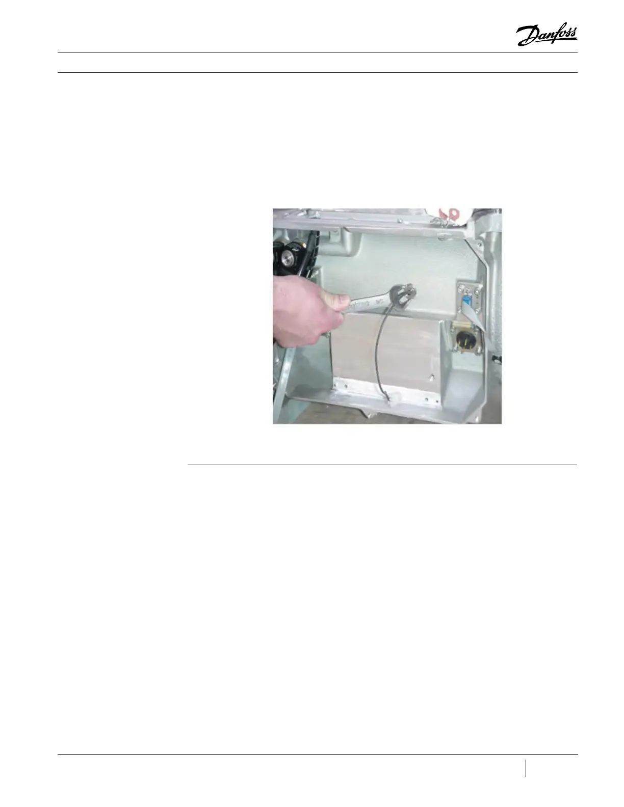
5. Remove the cavity temperature sensor. See
Figure 92 (Cavity Temperature Sensor Removal).
1. (Skip this step for all compressors that are
Major Revision “E” and later.) Apply a refrigerant
safe thread sealant to the cavity temperature
sensor threads (avoid thread-locking substances).
2. Insert the sensor and engage the first few
threads by hand.
3. Tighten the sensor to 13 Nm (9.5 ft.lb.).
4. Leak test compressor to appropriate pressure
and industry accepted standards.
5. Evacuate compressor to industry accepted
standards.
6. Reinstall the service side electronic modules.
7. Reinstall Service Side Cover.
6. Ensure housing threads are clean.
Figure 92 - Cavity
Temperature Sensor
Removal

 Loading...


