54 of 132
M-SV-001-EN Rev.E
3.7.4 Removal and
Installation
• • • CAUTION • • •
Removal of the Inverter mounting screws will release refrigerant. Isolation and recovery of the refrigerant must be performed by a
qualified service technician adhering to industry/ASHRAE standards.
1. Isolate the compressor power as described
in the “Electrical Isolation of the Compressor”
section of this manual.
2. Remove the Soft Start Board.
3. Remove the Mains Input terminal and bus bars.
4. Remove the DC capacitor and bus assembly.
5. Disconnect the ribbon cable from the Inverter.
6. Remove the copper tubes that connect the
motor bus bars to the Inverter.
Important: Do not remove the screws that
secure the Inverter to the compressor main
housing.
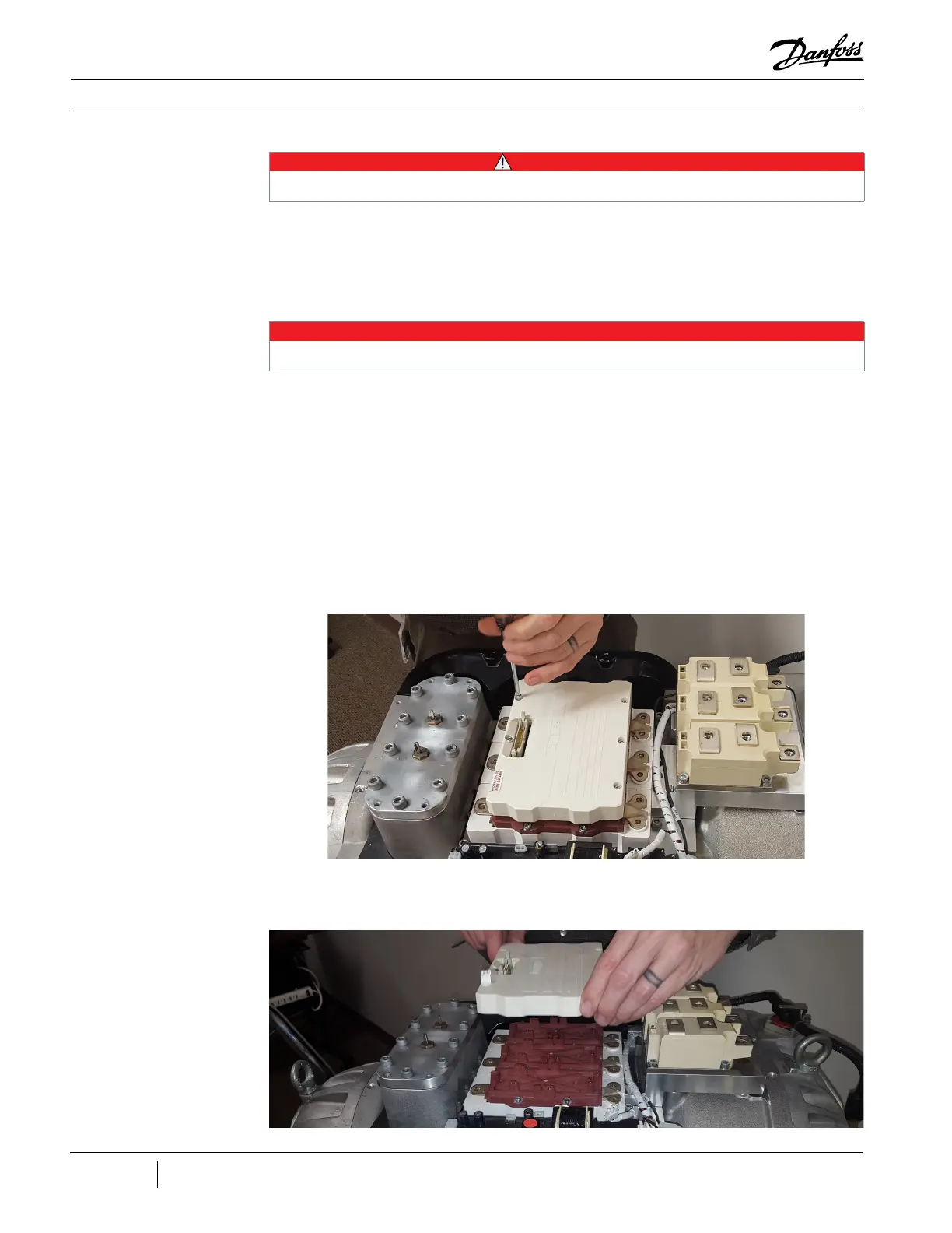
7. Unscrew the six (6) screws using a T15 Torx
bit. Begin on the outside and work towards the
center.
This section details the steps to remove and
install the IGBT Control Card (all models except
for the TT300/TG230) and also the entire Inverter
assembly. If the Inverter proves to be working
properly and the IGBT Control Card has been
confirmed to have failed, follow the removal and
installation steps for the IGBT Control Card.
3.7.4.1 IGBT Control Card
Removal
NOTE
The TT300/TG230 Compressor IGBT Control Cards are not serviceable.
Figure 45 - Driver Board
Screw Removal
Figure 46 - Driver Board
Removal
8. Carefully lift the driver board vertically.

 Loading...


