82 of 132
M-SV-001-EN Rev.E
Compressor Components
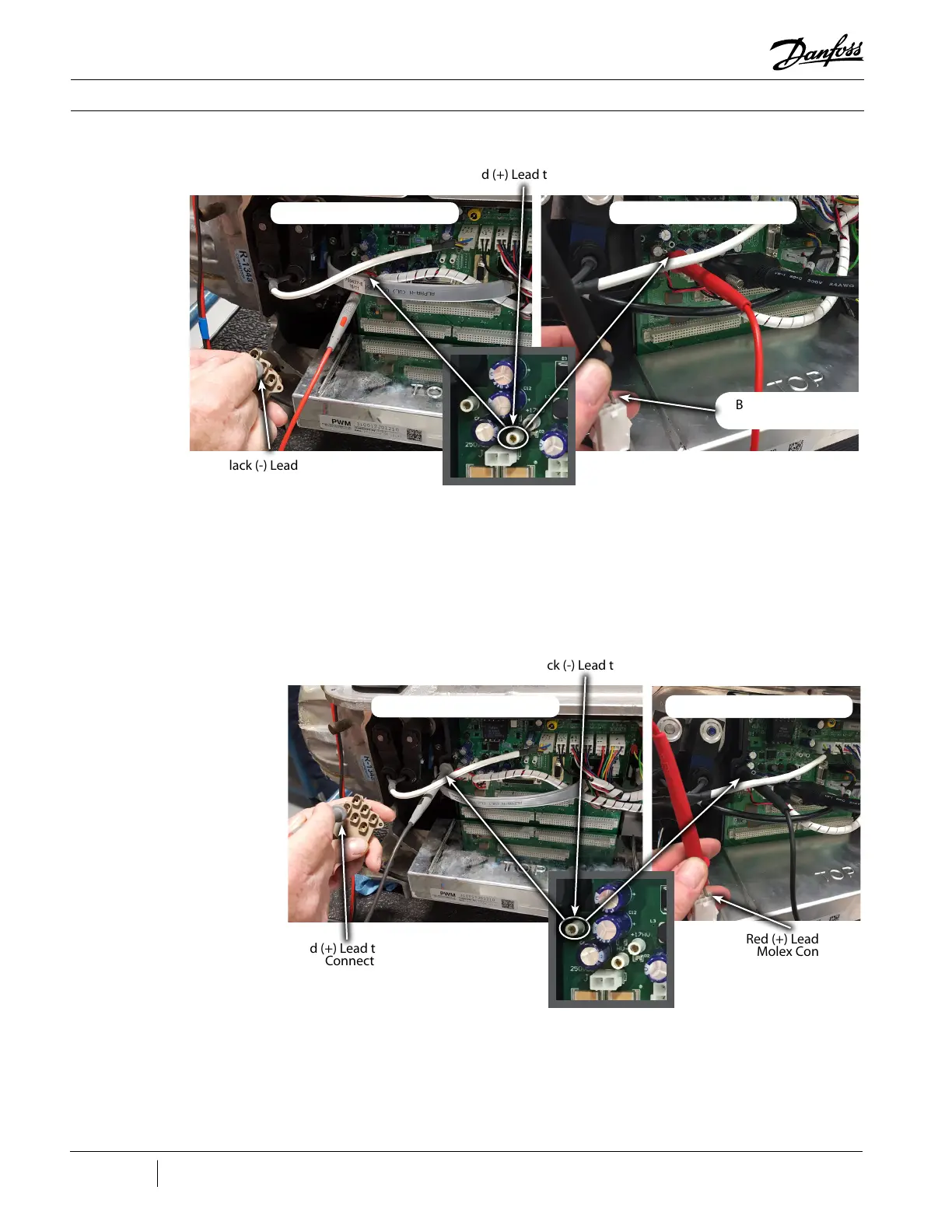
Figure 77 - Connecting Leads
to PWM Connector and HV-
Test Point
6. Repeat Step 3 for all 10 pin holes on both PWM
connectors.
7. Still set on diode measurement, place the black
(-) multimeter lead on the HV+ test point of the
Backplane and the red (+) multimeter lead in
the first pin hole of the PWM connector, ensure
the lead makes contact with the clip in the pin
hole. See Figure 78 (Connecting Leads to PWM
Connector and HV+ Test Point). The measured
voltage drop should be 0.39-0.46VDC.
8. Repeat Step 5 for all 10 pin holes of both PWM
connectors.
9. If any of the test results are out of the 0.39 -
0.46 VDC range, the PWM is defective and should
be replaced.
Figure 78 - Connecting Leads
to PWM Connector and HV+
Test Point
Red (+) Lead to HV-
Black (-) Lead to PWM
Molex Connector
Black (-) Lead to PWM
Connector
Red (+) Lead to PWM
Connector
Red (+) Lead to PWM
Molex Connector
Major Revision “E” and Earlier
Major Revision “F” and Later
Black (-) Lead to HV+
Major Revision “E” and Earlier
Major Revision “F” and Later

 Loading...


