37 of 132
M-SV-001-EN Rev.E
Compressor Components
Rigid 3/8 inch copper connection TT300/
TG230
• If connection is 3/8 inch rigid copper, a length
of 1/2 inch copper must be brazed into the braze
sleeve as above. A transition fitting should be
brazed to connect the 3/8 to 1/2 inch tubes.
Follow procedure as noted above in Rigid 1/2
Copper Connection section.
Important
• It should be noted that the inclusion of a
strainer within the connection body is intended
as a last resort backup only to prevent ingress of
debris that may block solenoid orifices or restrict
motor and power electronics cooling. It is not a
substitute for a correctly sized full-flow filter drier.
A filter drier must be installed in all instances. If it
is found that a filter drier is not installed and the
fitting is changed due to a field replacement of
the compressor, a filter drier must be included in
the line modification.
• If it is required to remove the fitting from the
housing for any reason, clean the O-ring, fitting
and housing threads, and apply a small amount
of O-ring lube before reassembly.
The terminal block is the location where the
compressor receives 3-Phase AC voltage, even
when not running. All compressors must be fitted
with class T fast-acting fuses to protect the solid
state Inverter. Danfoss Turbocor control does
NOT directly measure 3-phase power values.
All 3-phase voltage information displayed in
the SMT is calculated from DC bus voltage and
motor power as measured by the Inverter. The
input voltage varies between 380-575VAC at a
frequency of 50/60Hz.
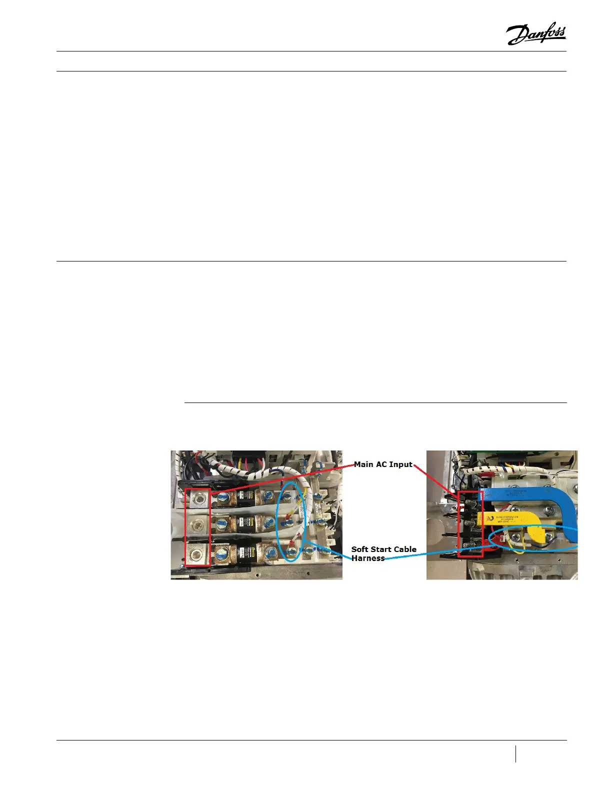
Refer to Figure 25 (Main AC Input Terminal) to
locate the AC voltage input terminal block and
bus bars.
The TT300/TG230 are the only compressors
where the Mains Input terminal connections
include in-line fuses.
The AC line power is routed to the SCRs by the
three main AC input bus bars and to the Soft
Start Board by the Soft Start Cable Harness to
allow control timing of the SCR circuits.
3.3 3-Phase Main Voltage
Input Terminal Block
3.3.1 Function
3.3.2 Connections
Figure 25 - Main AC Input
Terminal TT300/TG230
(left) TT350/TT400/TT500/
TT700/TG310/TG390/
TG520 (right)

 Loading...


