3 Parameter Description
3.1 Parameter Selection
The parameters are grouped into various parameter groups for easy selection of the correct parameter for optimal operation
of the frequency converter.
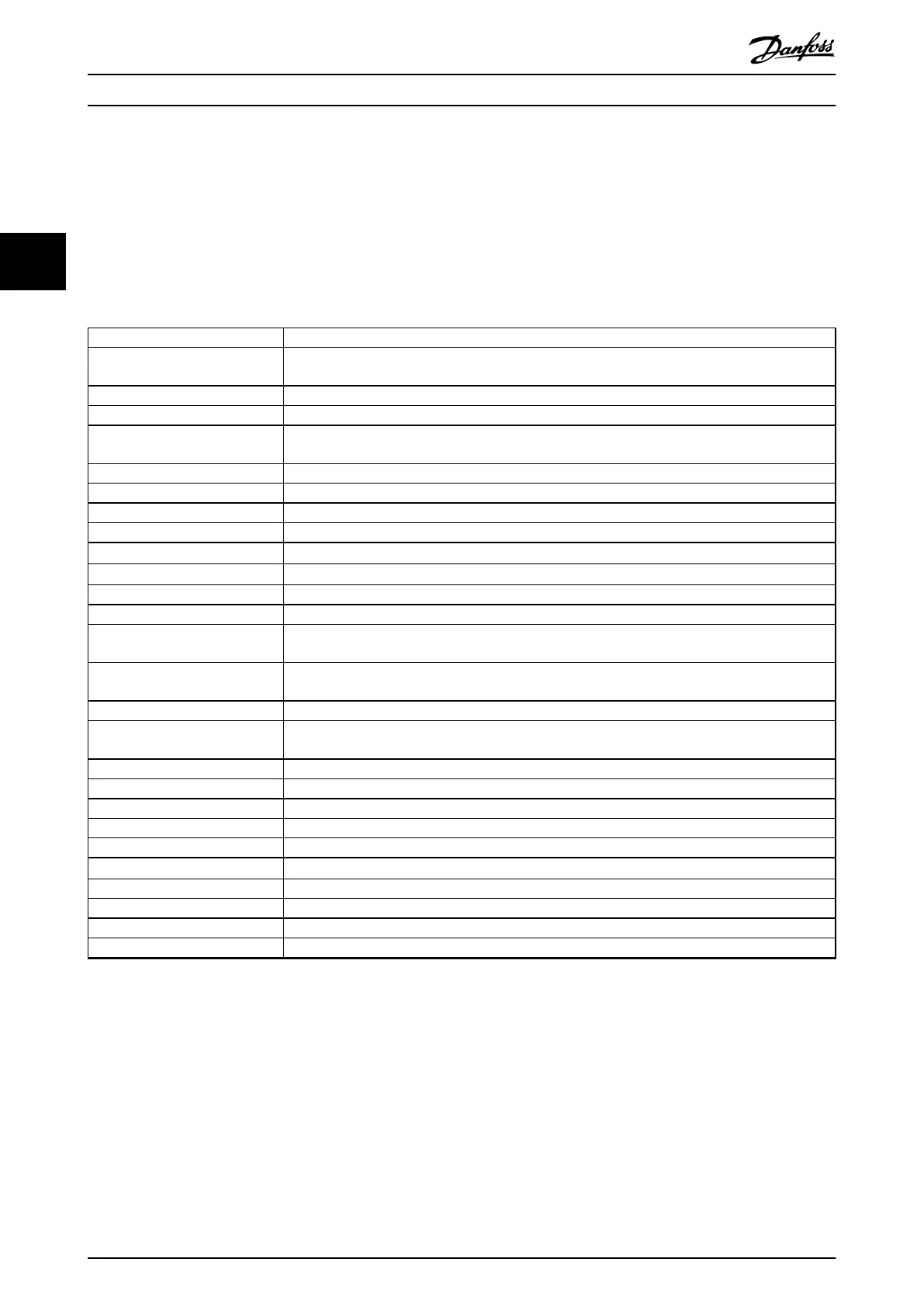
Overview of parameter groups
Group Function
0-** Operation and Display Parameters related to the basic functions of the frequency converter, function of the LCP keys, and
conguration of the LCP display.
1-** Load and Motor Parameters related to motor settings.
2-** Brakes Parameters related to brake features in the frequency converter.
3-** Reference/Ramps Parameters for the handling of reference, denitions of limitations, and conguration of the reaction
of the frequency converter to changes.
4-** Limits/Warnings Parameters for conguring limits and warnings.
5-** Digital In/Out Parameters for conguring the digital inputs and outputs.
6-** Analog In/Out Parameters for conguring the analog inputs and outputs.
8-** Communications and Options Parameter group for conguring communications and options.
9-** PROFIBUS
Parameter group for Probus-specic parameters (requires VLT
®
PROFIBUS DP MCA 101).
10-** CAN Fieldbus
Parameter group for DeviceNet-specic parameters (requires VLT
®
DeviceNet MCA 104).
13-** Smart Logic Parameter group for smart logic control.
14-** Special Functions Parameter group for conguring special frequency converter functions.
15-** Frequency Converter
Information
Parameter group containing frequency converter information such as operating data, hardware
conguration, and software versions.
16-** Data Readouts Parameter group for data readouts, for example, actual references, voltages, control, alarm, warning,
and status words.
18-** Data Readouts 2 This parameter group contains the last 10 preventive maintenance logs.
20-** FC Closed Loop This parameter group is used for conguring the closed loop PID controller that controls the output
frequency of the unit.
21-** Extended Closed Loop Parameters for conguring the 3 extended closed loop PID controllers.
22-** Application Functions Parameters for water applications.
23-** Time-based Functions Parameters for actions to be performed on a daily or weekly basis.
24-** Application Functions 2 Parameters for the frequency converter bypass.
25-** Cascade Controller Parameters for conguring the basic cascade controller for sequence control of multiple pumps.
26-** Analog I/O Option MCB 109
Parameters for conguring the VLT
®
Analog I/O Option MCB 109.
29-** Water Application Functions Parameters for setting water-specic functions.
30-** Special Features Parameters for conguring the special features.
31-** Bypass Option Parameters for conguring the bypass function.
35-** Sensor Input Option Parameters for conguring the sensor input function.
Table 3.1 Parameter Groups
Parameter descriptions and selections are shown in the
graphical LCP or the numeric LCP. See chapter 2 How to
Program for details. Access the parameters by pressing
[Quick Menu] or [Main Menu] on the LCP. The Quick Menu is
used primarily for commissioning the unit at start-up by
providing the parameters necessary to start operation. The
Main Menu provides access to all parameters for detailed
application programming.
All digital input/output and analog input/output terminals
are multifunctional. All terminals have factory default
functions suitable for most water applications. If other
special functions are required, they must be programmed
in parameter groups 5-** Digital In/out or 6-** Analog In/
out.
Parameter Description
VLT
®
AQUA Drive FC 202
26 Danfoss A/S © 05/2018 All rights reserved. MG20OB02
33

 Loading...


