2.2.2 Quick Transfer of Parameter Settings
between Multiple Frequency
Converters
Once the set-up of a frequency converter is complete,
store the data in the LCP or on a PC via MCT 10 Set-up
Software.
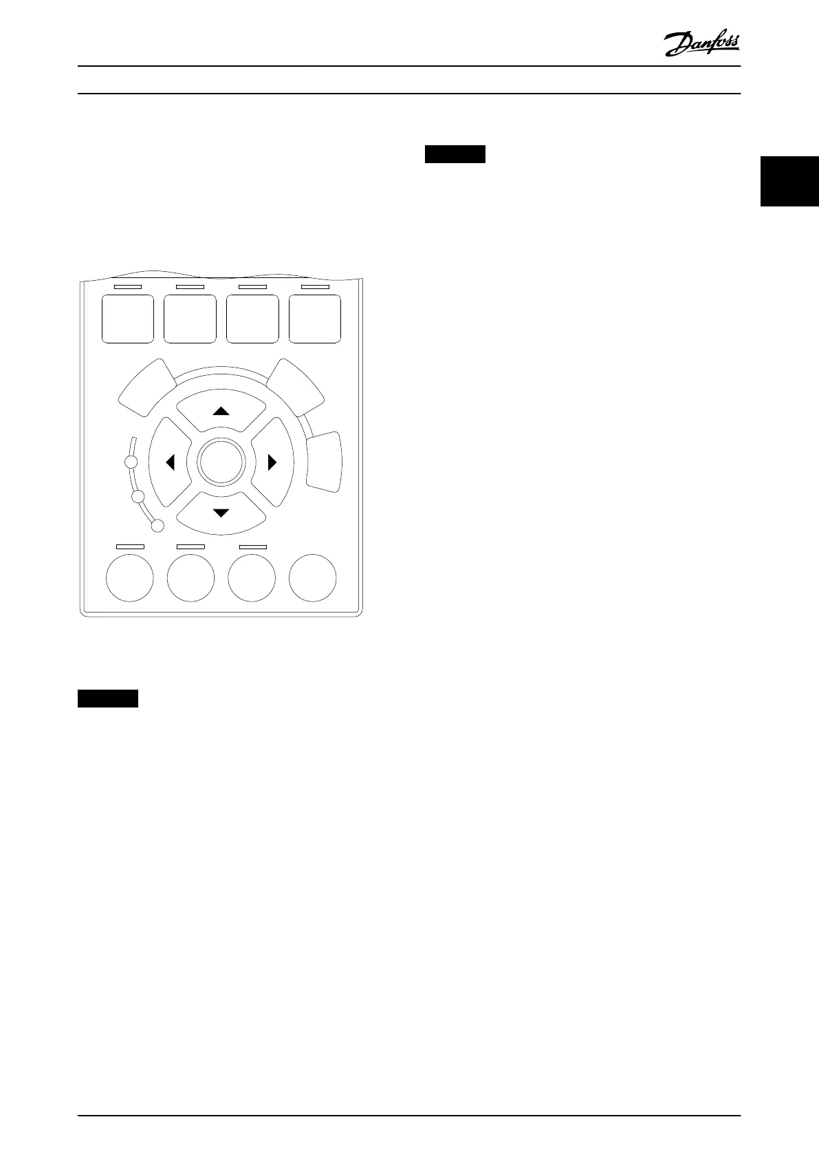
Auto
on
Reset
Hand
on
O
Status
Quick
Menu
Main
Menu
Alarm
Log
Back
Cancel
Info
OK
On
Alarm
Warn.
130BA027.10
Illustration 2.10 LCP
Data storage in LCP
NOTICE
Stop the motor before performing this operation.
To store the data in the LCP:
1. Go to parameter 0-50 LCP Copy.
2. Press the [OK] key.
3. Select [1] All to LCP.
4. Press the [OK] key.
All parameter settings are now stored in the LCP indicated
by the progress bar. When 100% is reached, press [OK].
Connect the LCP to another frequency converter and copy
the parameter settings to this frequency converter as well.
Data transfer from LCP to frequency converter
NOTICE
Stop the motor before performing this operation.
To transfer the data from the LCP to the frequency
converter:
1. Go to parameter 0-50 LCP Copy.
2. Press the [OK] key.
3. Select [2] All from LCP.
4. Press the [OK] key.
The parameter settings stored in the LCP are now
transferred to the frequency converter indicated by the
progress bar. When 100% is reached, press [OK].
2.2.3 Display Mode
In normal operation, up to 5 dierent operating variables
can be indicated continuously in the middle section: 1.1,
1.2, and 1.3, as well as 2 and 3.
2.2.4 Display Mode - Selection of Readouts
Press [Status] to toggle between 3 status readout screens.
Operating variables with dierent formatting are shown in
each status screen. For more information, see the examples
in this chapter.
Several values or measurements can be linked to each of
the shown operating variables. The values or
measurements to be shown can be dened via the
following parameters:
•
Parameter 0-20 Display Line 1.1 Small.
•
Parameter 0-21 Display Line 1.2 Small.
•
Parameter 0-22 Display Line 1.3 Small.
•
Parameter 0-23 Display Line 2 Large.
•
Parameter 0-24 Display Line 3 Large.
Access the parameters via [Quick Menu], Q3 Function Set-
ups, Q3-1 General Settings, Q3-13 Display Settings.
Each readout parameter selected in parameter 0-20 Display
Line 1.1 Small to parameter 0-24 Display Line 3 Large has its
own scale and digits after a decimal point. The higher
numeric value of a parameter, the fewer digits are shown
after the decimal point.
Example: Current readout 5.25 A; 15.2 A; 105 A.
See parameter group 0-2* LCP Display for further details.
How to Program Programming Guide
MG20OB02 Danfoss A/S © 05/2018 All rights reserved. 17
2 2

 Loading...


