3.13 Parameters 14-** Special Functions
3.13.1 14-0* Inverter Switching
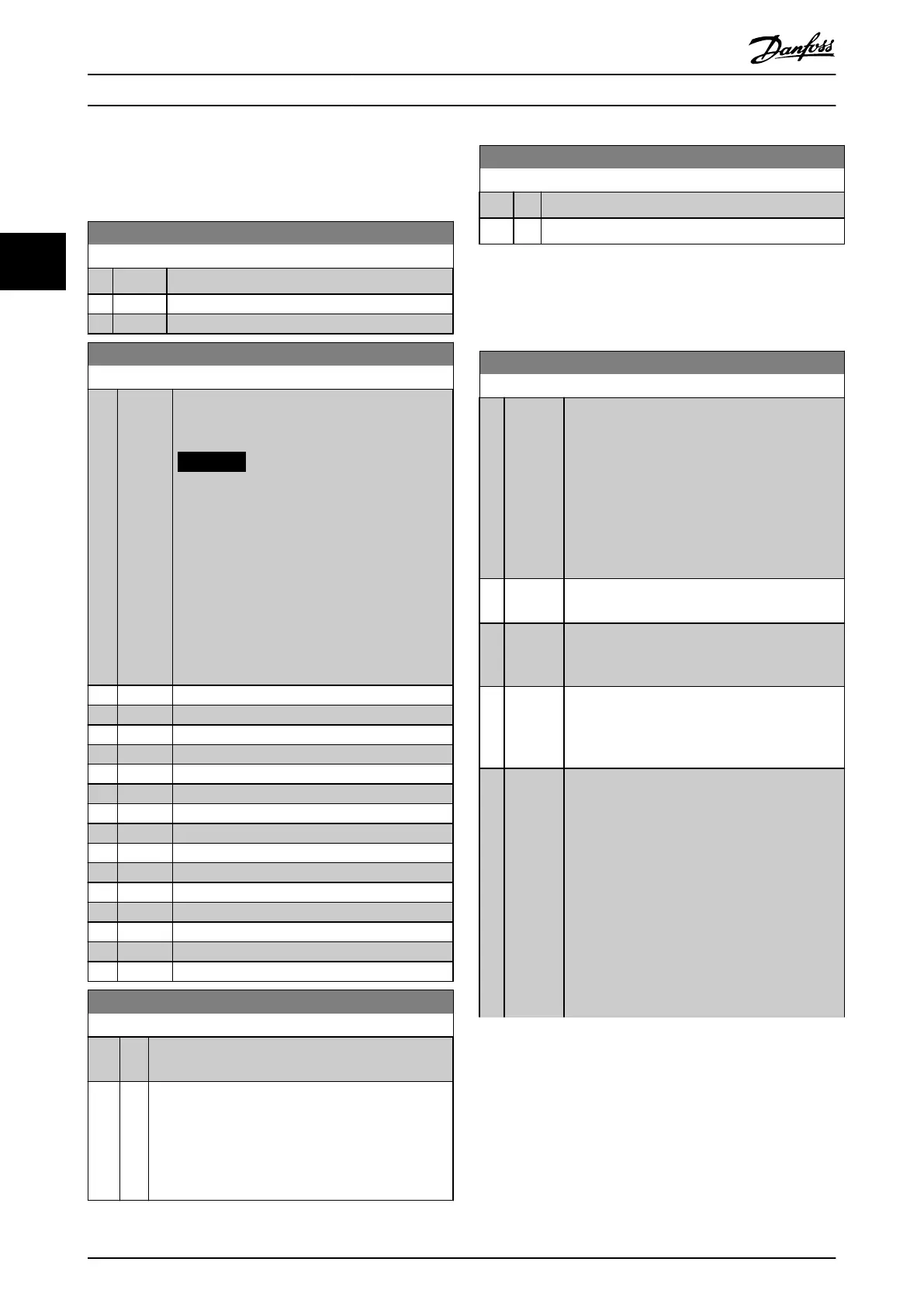
14-00 Switching Pattern
Option: Function:
Select the switching pattern: 60° AVM or SFAVM.
[0] 60 AVM
[1] SFAVM
14-01 Switching Frequency
Option: Function:
Select the inverter switching frequency. Changing
the switching frequency can help reduce acoustic
noise from the motor.
NOTICE
The output frequency value of the
frequency converter must never exceed
1/10 of the switching frequency. When the
motor is running, adjust the switching
frequency in parameter 14-01 Switching
Frequency until the motor is as noiseless as
possible. See also
parameter 14-00 Switching Pattern. For
information about derating, see the
relevant design guide.
[0] 1.0 kHz
[1] 1.5 kHz
[2] 2.0 kHz
[3] 2.5 kHz
[4] 3.0 kHz
[5] 3.5 kHz
[6] 4.0 kHz
[7] 5.0 kHz
[8] 6.0 kHz
[9] 7.0 kHz
[10] 8.0 kHz
[11] 10.0 kHz
[12] 12.0kHz
[13] 14.0 kHz
[14] 16.0kHz
14-03 Overmodulation
Option: Function:
[0] O Selects no overmodulation of the output voltage to
avoid torque ripple on the motor shaft.
[1] * On The overmodulation function generates an extra
voltage of up to 8% of U
max
output voltage without
overmodulation. This extra voltage results in an extra
torque of 10–12% in the middle of the oversyn-
chronous range (from 0% at nominal speed, rising to
approximately 12% at double nominal speed).
14-04 Acoustic Noise Reduction
Option: Function:
[0] * O No change of the acoustic motor switching noise.
[1] On Select to reduce the acoustic noise from the motor.
3.13.2 14-1* Mains On/O
Parameters for conguring mains failure monitoring and
handling.
14-10 Mains Failure
Option: Function:
Select the function by which the frequency
converter must act when the threshold set in
parameter 14-11 Mains Fault Voltage Level has been
reached or a Mains Failure Inverse command is
activated via 1 of the digital inputs (parameter
group 5-1* Digital Inputs).
Only selections [0] No function, [3] Coasting, or [6]
Alarm are available when parameter 1-10 Motor
Construction is set to [1] PM, non-salient SPM.
[0]
*
No
function
The energy left in the capacitor bank is used to
run the motor, but is discharged.
[1] Ctrl.
ramp-
down
The frequency converter performs a controlled
ramp down. Parameter 2-10 Brake Function must
be set to [0] O.
[3] Coasting The frequency converter turns o and the
capacitor bank backs up the control card, thus
ensuring a faster restart when mains reconnect (at
short power zags).
[4] Kinetic
back-up
Kinetic back-up ensures that the frequency
converter keeps running as long as there is
energy in the system due to the inertia from
motor and load. This is done by converting the
mechanical energy to the DC link and maintaining
control of the frequency converter and motor.
This can extend the controlled operation,
depending on the inertia in the system. For fans,
it is typically several seconds; for pumps up to 2 s;
and for compressors only for a fraction of a
second. Many industry applications can extend
controlled operation for many seconds, which is
often enough time for the mains to return.
Parameter Description
VLT
®
AQUA Drive FC 202
132 Danfoss A/S © 05/2018 All rights reserved. MG20OB02
33

 Loading...


